

Low-voltage distribution area dispersion reactive compensation method based on wireless network
A low-voltage power distribution and decentralized compensation technology, which is applied in the direction of reactive power compensation, reactive power adjustment/elimination/compensation, etc., can solve the problem of poor power factor improvement effect at the load end of the low-voltage power grid, inability to effectively reduce the load current of the low-voltage power grid, and inability to compensate Low-voltage grid power factor and other issues, to achieve the effect of improving the capacitor commissioning rate and service life, reducing the load current, and improving the service life
- Summary
- Abstract
- Description
- Claims
- Application Information
AI Technical Summary
Problems solved by technology
Method used
Image

Examples
Embodiment Construction
[0014] The present invention will be further described in detail below in conjunction with the accompanying drawings and through specific embodiments. The following embodiments are only descriptive, not restrictive, and cannot limit the protection scope of the present invention.
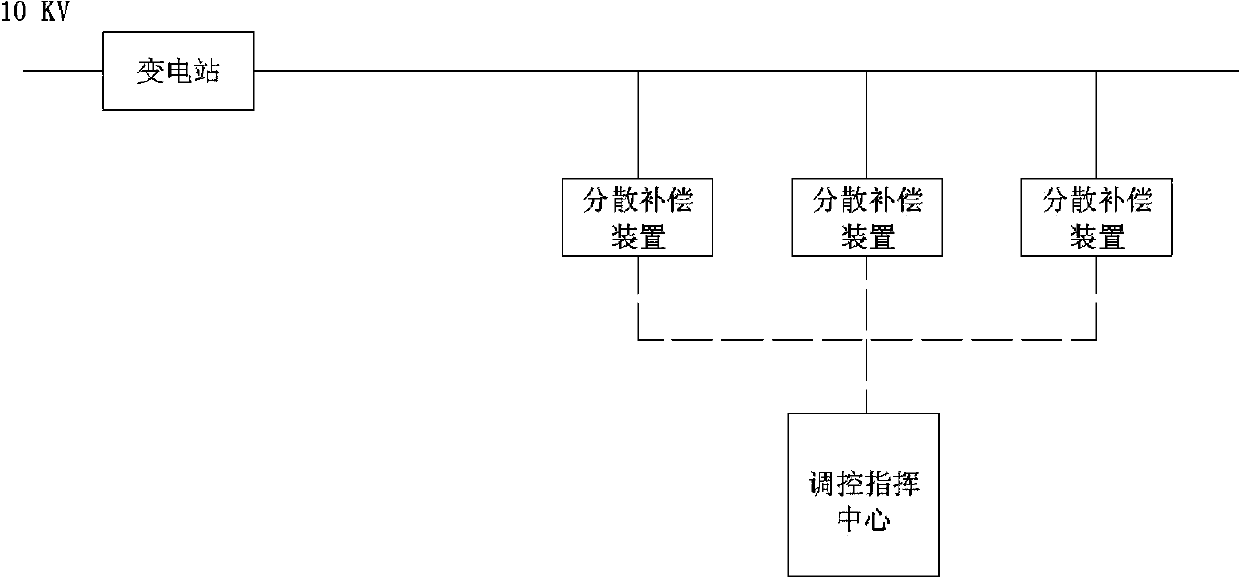
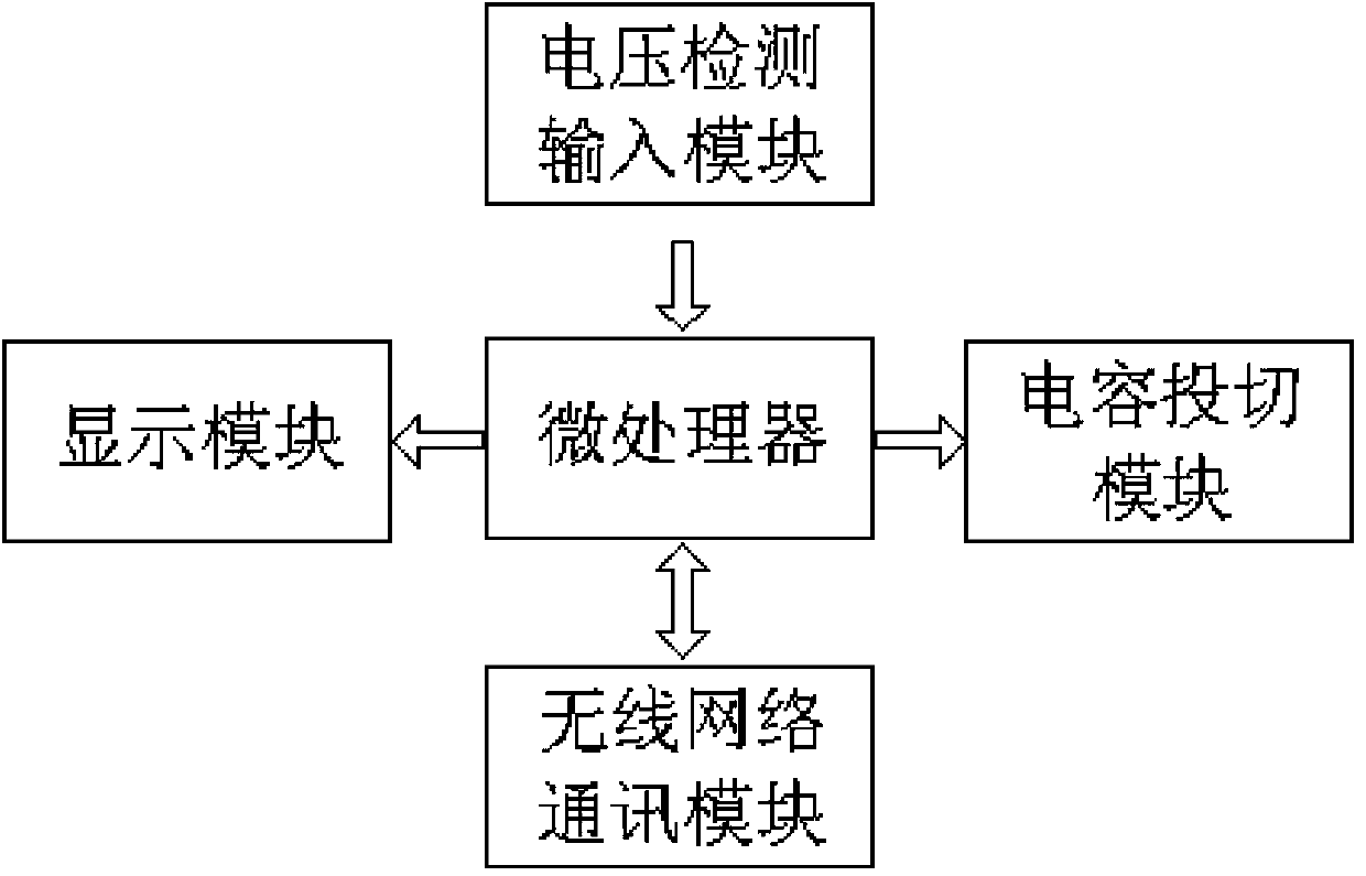
[0015] A wireless network-based decentralized reactive power compensation method for low-voltage distribution stations. A distributed compensation device is installed at the ends of multiple sub-lines of the 10kV power grid through the substation distribution output line or in the load concentration area. The decentralized compensation device adopts Non-inrush capacitor switcher, the specific structure is attached figure 2 As shown, it includes a microprocessor, a voltage detection input module, a capacitor switching module, a display module and a wireless network communication module. The input end of the voltage detection input module is connected to the transmission line, and the output end of the...
PUM
 Abstract
Description
Claims
Application Information