Sending method and device for channel state information-reference symbol (CSI-RS)
A technology of CSI-RS and transmission method, which is applied in the field of channel state information reference symbols, can solve problems such as low system efficiency and large CSI-RS resource overhead, and achieve the effect of reducing overhead and improving capacity
- Summary
- Abstract
- Description
- Claims
- Application Information
AI Technical Summary
Problems solved by technology
Method used
Image

Examples
Embodiment 1
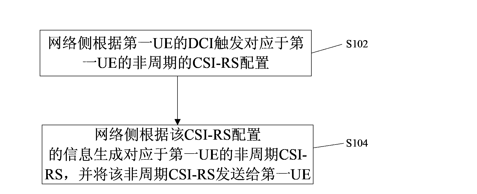
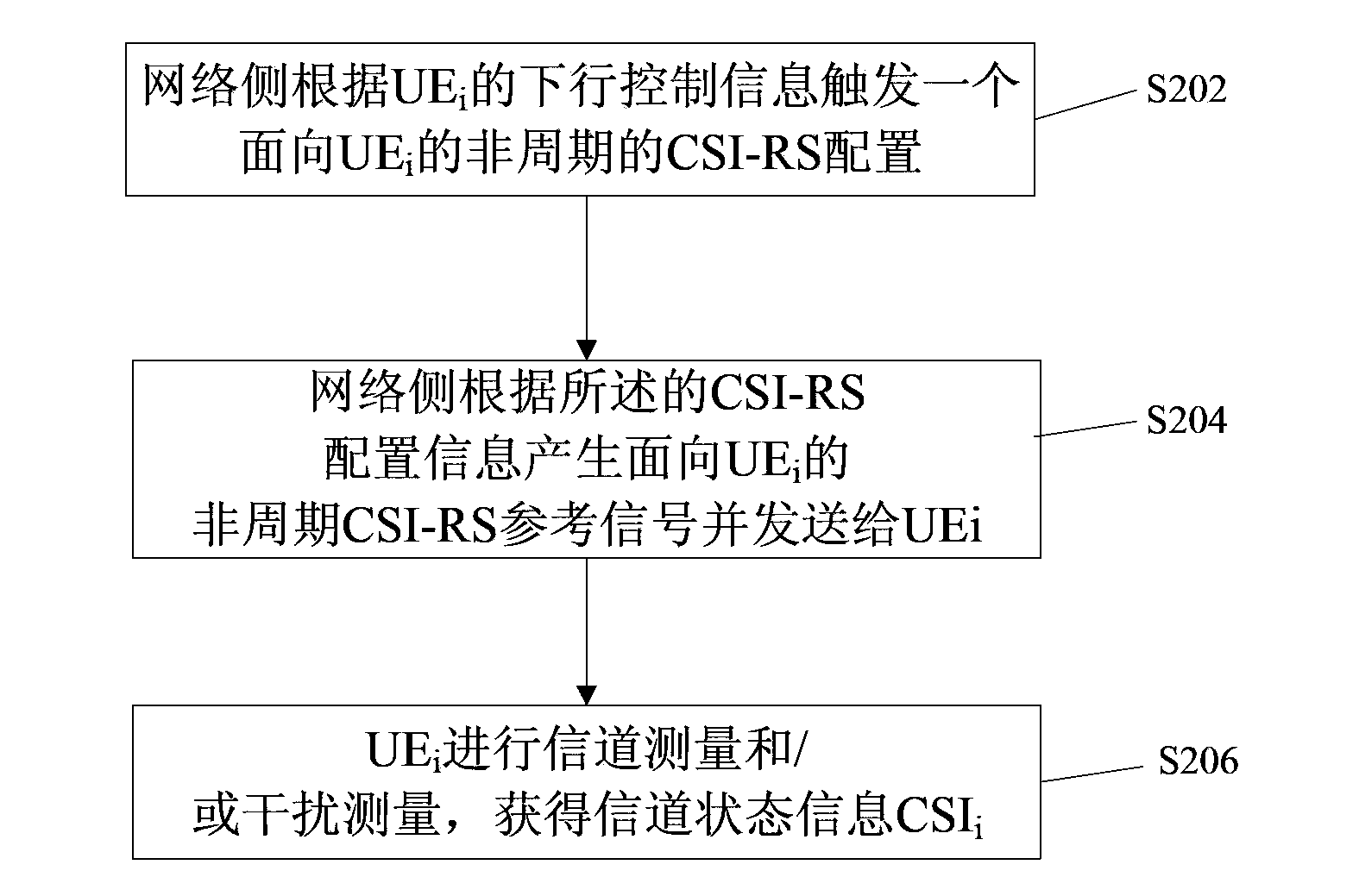
[0066] The embodiment of the present invention also provides a CSI-RS sending method, figure 2 is a flow chart of a CSI-RS sending method according to Embodiment 1 of the present invention, such as figure 2 As shown, the method includes:
[0067] Step S202, the network side according to UE i The downlink control information triggers a UE-oriented i The aperiodic CSI-RS configuration, where the UE i Indicates the i-th user;
[0068] Step S204, the network generates UE-oriented i The aperiodic CSI-RS reference signal, and send the reference signal to the UE i ;
[0069] Step S206, UE i Perform channel measurement and / or interference measurement according to the aperiodic CSI-RS reference signal, and obtain channel state information CSI according to the measurement result i .
[0070] Wherein, step S206 may have the following three implementations:
[0071] Implementation method 1, if the aperiodic CSI-RS reference signal is a non-zero power CSI-RS signal, the UE i C...
Embodiment 2
[0082] An embodiment of the present invention provides a method for sending a CSI-RS, the method including:
[0083] Step 1, the network side according to the UE i The downlink control information DCI i trigger a UE-oriented i The aperiodic CSI-RS configuration; where, UE i Indicates the i-th user;
[0084] Step 2, the network side generates UE-oriented i The aperiodic CSI-RS reference signal, and send the reference signal to the UE i ;
[0085] Step 3, UE i Perform channel measurement according to the aperiodic CSI-RS reference signal, and obtain channel state information CSI according to the measurement result i . Wherein, the aperiodic CSI-RS reference signal is a non-zero power CSI-RS signal, and the UE i Channel measurement based on aperiodic CSI-RS reference signal to obtain channel state information CSI i .
[0086] Wherein, all aperiodic CSI-RS reference signals may appear on subframes with a fixed period, and the period may be 5 ms or an integer multiple of...
Embodiment 3
[0108] The main content of this embodiment is the same as that of Embodiment 2, except that in Embodiment 2, the UE i The aperiodic CSI-RS signal and the UE j The periodic CSI-RS signals appear in different subframes, and in this embodiment, the UE i The aperiodic CSI-RS signal and the UE j The periodic CSI-RS signals appear in the same subframe.
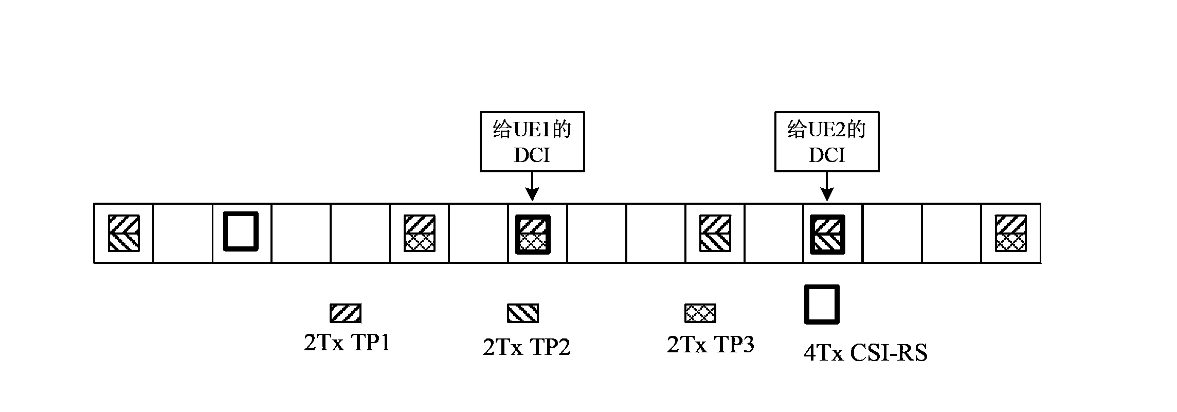
[0109] The implementation process of this embodiment will be described in more detail below through a specific example. In this embodiment, aperiodic CSI-RS is used for channel measurement, and aperiodic CSI-RS triggered by different UEs appears in the same subframe in, such as Figure 4 shown.
[0110] The content of this example is basically the same as that of the specific example in Embodiment 2. The network side configures five CSI-RS reference signals for the terminal side (which can be UE1 or UE2). The five reference signals in this embodiment 1, 2, 3, and 5 in are the same as 1, 2, 3, and 5 in the five reference signals...
PUM
 Abstract
Description
Claims
Application Information
 - Generate Ideas
- Intellectual Property
- Life Sciences
- Materials
- Tech Scout
- Unparalleled Data Quality
- Higher Quality Content
- 60% Fewer Hallucinations
Browse by: Latest US Patents, China's latest patents, Technical Efficacy Thesaurus, Application Domain, Technology Topic, Popular Technical Reports.
© 2025 PatSnap. All rights reserved.Legal|Privacy policy|Modern Slavery Act Transparency Statement|Sitemap|About US| Contact US: help@patsnap.com