Suction nozzle inspection device

A technology for inspection devices and photographing devices, applied to electrical components, electrical components, etc., can solve the problems of reduced suction force of electronic components, difficulty in visually confirming nozzle holes, etc., and achieve good workability

Active Publication Date: 2013-11-13
FUJI KK
View PDF8 Cites 24 Cited by
  • Summary
  • Abstract
  • Description
  • Claims
  • Application Information

AI Technical Summary

Problems solved by technology

[0006] However, since the inside of the nozzle hole is difficult to visually confirm, it is diffi

Method used


Image

  • Suction nozzle inspection device
  • Suction nozzle inspection device
  • Suction nozzle inspection device

Examples


Example

[0119] (Other implementation methods)

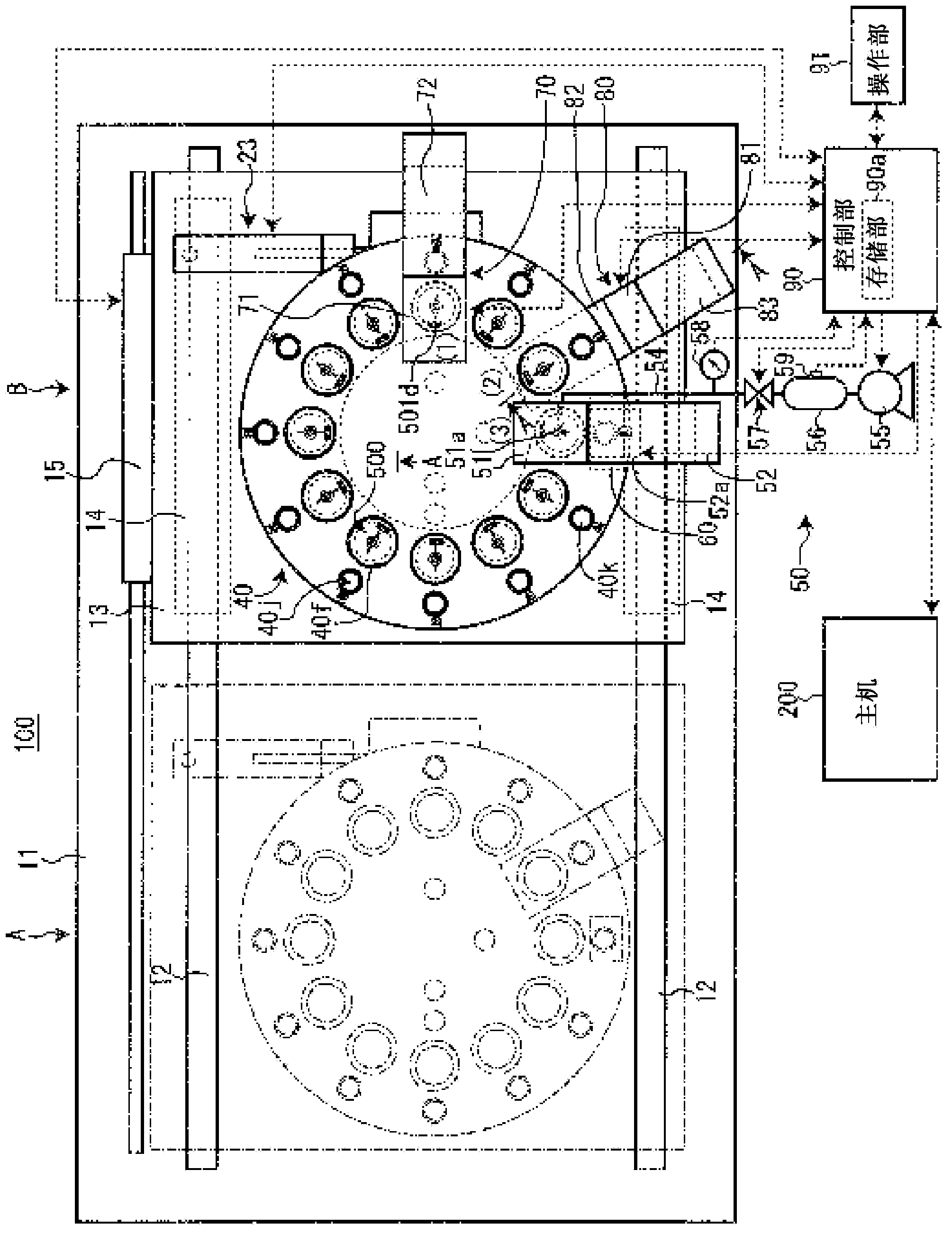
[0120] In addition, in the embodiment described above, the pump 55 supplies air to the air passage 51a of the nozzle connection portion 51, and the flow rate detection sensor 58 detects the flow rate of air supplied to the nozzle hole 502f through the nozzle connection portion 51 by the pump 55 The control unit 90 determines the cleaning state of the nozzle hole 502f based on the flow rate of air detected by the flow rate detection sensor 58. However, it may also be an embodiment in which the pump 55 sucks air from the air passage 51a of the nozzle connection portion 51, and the flow rate detection sensor 58 detects the amount of air sucked from the nozzle hole 502f by the pump 55 via the nozzle connection portion 51 For the flow rate, the control unit 90 determines the cleaning state of the nozzle hole 502f based on the flow rate of air detected by the flow rate detection sensor 58.

[0121] In addition, in the embodiment described above, t...


PUM


Abstract

Provided is a suction nozzle inspection device which can inspect the cleaning state of a suction nozzle after cleaning. The suction nozzle inspection device has a rotary device (20), a suction nozzle holding tray (40), a suction nozzle connecting part (51), a pump, a flow detection part and a cleaning state determination part, wherein the rotary device (20) enables a rotary table (30) to rotate by a specified angle, the suction nozzle holding tray (40) is detachably arranged on the rotary table (30) and is provided with plural suction nozzle holding parts (40f) for vertically holding the suction nozzle (500) at equal intervals at the periphery, the suction nozzle connecting part (51) is arranged to move vertically and is connected and communicated with a suction nozzle hole of the suction nozzle (500), the pump supplies air to the suction nozzle connecting part (51), the flow detection part detects the flow of air supplied to the suction nozzle from the suction nozzle connecting part via the pump, and the cleaning state determination part determines the cleaning state of the suction nozzle (500) based on the flow of air detected by the flow detection part.

Description

technical field [0001] The invention relates to a device for inspecting suction nozzles of suction elements. Background technique [0002] Conventionally, the electronic component mounting apparatus shown in patent document 1 is proposed. Such an electronic component mounting apparatus is a device that absorbs supplied electronic components with a suction nozzle and transports them to a mounting position of the electronic substrate to mount the electronic components on the electronic substrate. [0003] With the operation of the electronic component mounting apparatus, foreign matter such as solder and dust accumulates in the nozzle hole of the nozzle. As a result, the adsorption force of the electronic components by the suction nozzle is reduced, and in the worst case, the electronic components cannot be adsorbed by the suction nozzle or the electronic components adsorbed by the suction nozzle fall off, which may produce defective substrates. Therefore, the suction nozzle...

Claims


Application Information

Patent Timeline
IPC IPC(8): H05K13/04H05K13/08
CPCH05K13/0408H05K13/08
Inventor 手岛力茂
Owner FUJI KK
Why Eureka
Try Eureka