Ceramic pressure measuring cell

A technology for measuring units and pressure, which is applied in measuring devices, measuring fluid pressure, measuring fluid pressure through electromagnetic components, etc., and can solve problems such as inability to manufacture

Active Publication Date: 2013-11-13
EHNDRESS KHAUZER GMBKH KO KG
View PDF5 Cites 7 Cited by
  • Summary
  • Abstract
  • Description
  • Claims
  • Application Information

AI Technical Summary

Problems solved by technology

However, there is a limit to this because the joint between the platform and the measuring membrane body through which it is made, determines the active hard solder or braze, the material thickness of the ring is subject to certain tolerances and cannot be made as thin as desired

Method used


Image

  • Ceramic pressure measuring cell
  • Ceramic pressure measuring cell
  • Ceramic pressure measuring cell

Examples


Embodiment Construction

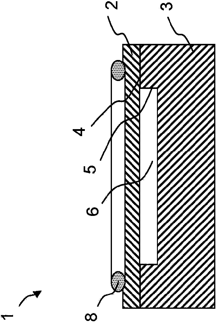
[0029] figure 1 The pressure measuring cell 1 shown in includes a measuring membrane 2 and a platform 3 , wherein the measuring membrane is pressure-tightly connected to the platform along a laser-welded peripheral joint. The measuring membrane 2 has a substantially circular, plate-like shape with a diameter of, for example, 1 cm to 6 cm, and a material thickness of not less than 50 μm and not more than, for example, 2500 μm. The platform 3 here has the same diameter as the measuring membrane 2 , the material thickness of which amounts to a few millimeters to several centimeters. Preferably, the platform is dimensioned such that it undergoes at most negligible deformation under the pressure load of the measuring membrane 2 . On the side of the measuring membrane at the end face of the platform 3, a cavity 5 is formed in order to form a pressure chamber 6 between the measuring membrane 2 and the platform 3, in which the measuring reference pressure is regularized, according to...


PUM

PropertyMeasurementUnit
diameteraaaaaaaaaa
thicknessaaaaaaaaaa

Abstract

A pressure measuring cell includes at least one ceramic measuring membrane body; and at least one ceramic platform, wherein the measuring membrane body is connected with the platform along an annular, peripheral joint. The joint is formed as a welded connection between the measuring membrane body and the platform, wherein the measuring membrane body has a pressure-dependently deformable measuring membrane. A pressure sensor includes a pressure measuring cell and a housing, wherein the pressure measuring cell is held by the housing, and wherein the pressure measuring cell closes a housing opening, through which the pressure measuring cell communicates with an environment of the housing. A seal is clamped between a sealing surface surrounding the opening of the housing and a sealing surface of the pressure measuring cell.

Description

technical field [0001] The invention relates to a ceramic pressure measuring cell having at least one measuring membrane and a platform, wherein the measuring membrane is connected to the platform along an annular joint. Materials known for this joint are glass and active hard solder, or braze. For example, a pressure sensor bonded by glass solder is disclosed in DE39420102B. In the still unpublished applications DE 1020106365.9, DE 102009046844.7, DE 102009054909.9 an overview of the different methods for producing joints by zirconium-nickel-titanium, active hard solder or copper solder is given and presented here as present There are technical references to these documents. The above-mentioned materials basically fulfill their purpose, ie they serve to bond the parts of the pressure measuring cell to one another. However, the use of these materials leads to limitations in the design of the measuring cell. Background technique [0002] The basic reason for this is the l...

Claims


Application Information

Patent Timeline
Patent Type & Authority Applications(China)
IPC IPC(8): G01L9/00
CPCG01L9/00G01L9/0075
Inventor 安德烈·贝林格尔武尔费特·德鲁斯迈克尔·菲利普斯安德烈亚斯·罗斯贝格埃尔克·施密特
Owner EHNDRESS KHAUZER GMBKH KO KG
Why Eureka
Try Eureka