Fiber brag grating dynamic high-pressure transducer

A technology of high pressure sensor and optical fiber grating, which is applied in the direction of fluid pressure measurement using optical methods, can solve the problems of pressure measurement that is not suitable for high frequency response and low pressure sensitivity, and achieves convenient and fast production, strong anti-interference ability, and structural simple effect

Active Publication Date: 2014-04-09
THE THIRD ENG CORPS RES INST OF THE HEADQUARTERS OF GENERAL STAFF PLA
View PDF6 Cites 8 Cited by
  • Summary
  • Abstract
  • Description
  • Claims
  • Application Information

AI Technical Summary

Problems solved by technology

However, what the fiber grating can directly respond to is the change of strain and temperature. When the fiber grating is used as a pressure sensor, due to the low pressure sensitivity of the bare fiber grating, it is necessary to use different packaging ...

Method used


Image

  • Fiber brag grating dynamic high-pressure transducer
  • Fiber brag grating dynamic high-pressure transducer

Examples


Embodiment Construction

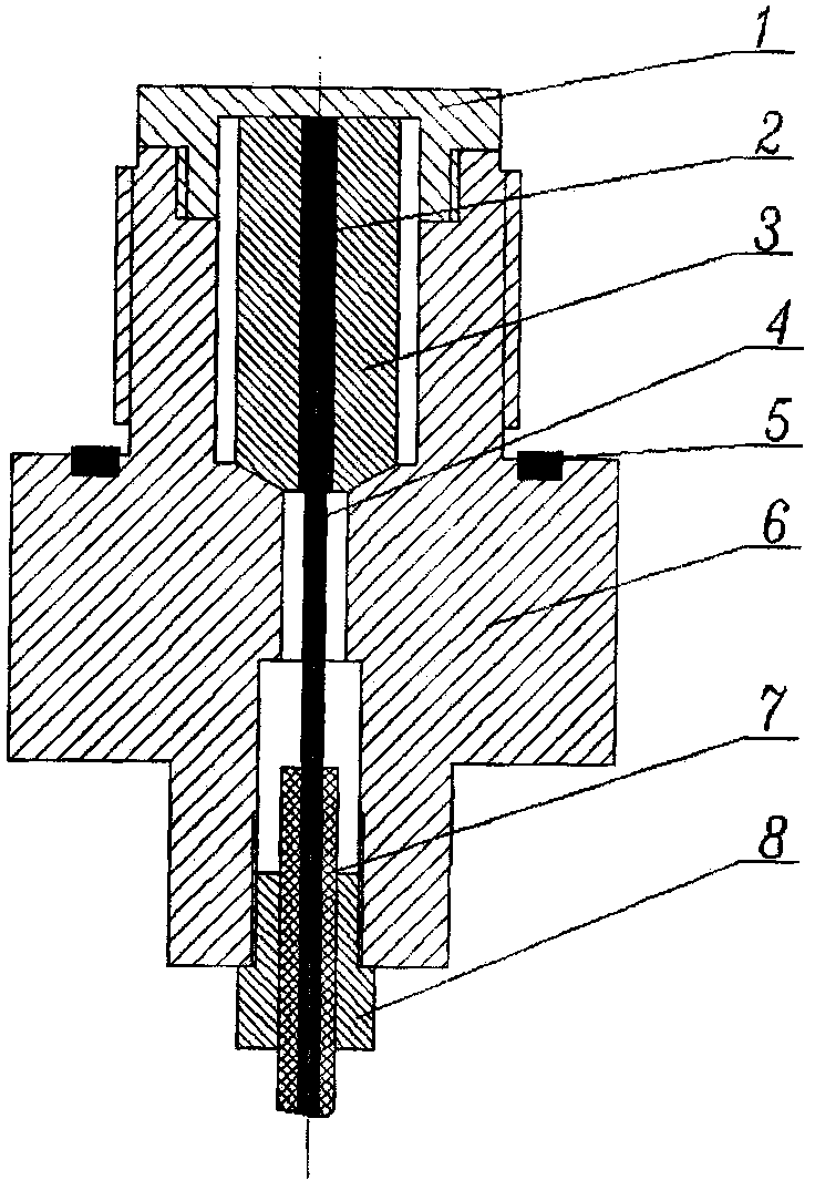
[0016] see figure 1 , The present invention consists of a diaphragm body 1, a filling glue 2, a support column 3, an optical fiber 4 containing a grating (FBG), a sealing gasket 5, an installation shell 6, an optical fiber sheath 7, and a fixed joint 8. The diaphragm body 1 and the front end of the installation housing 6 are fixed to form the pressure-sensitive surface of the sensor. The grating (FBG) on the optical fiber 4 is pasted on the surface of the inner hole of the supporting column 3 in parallel with the axial direction and filled with filling glue 2 in the hole. The upper end surface of the supporting column 3 is in close contact with the diaphragm body 1, the lower end surface of the supporting column 3 and the installation shell 6 adopt a conical contact surface, and the optical fiber 4 inserted into the optical fiber sheath 7 is fixed to the installation shell through a fixed joint 8 At the lower end of the body 6, the sealing gasket 5 is placed in the groove on t...


PUM


Abstract

The invention discloses a fiber brag grating dynamic high-pressure transducer which comprises a membrane body, a supporting column, a grating containing fiber brag, an installation shell body, an optical fiber protecting bush and a fixing connector. The membrane body is fixed at the front end of the installation shell body and then forms a pressure sensing face of the sensor. The grating is parallelly pasted to the surface of an inner hole of the supporting column in the axial direction. The hole is full of filling glue. The upper end face of the supporting column is in tight contact with the membrane body. A conical type contact face is adopted between the lower end face of the supporting column and the installation shell body. The optical fiber arranged in the fiber protecting bush in a sleeved mode is fixed at the lower end of the installation shell body through the fixing connector. The fiber brag grating dynamic high-pressure transducer is characterized in that pressure deformation of the circular supporting column is utilized to convert outside pressure into strain changes of the fiber brag grating (FBG), and pressure sensing is realized through measurement of strain. The sensor is firm in structure, high-temperature resistant, strong impact vibration resistant, free of electromagnetic interference, especially suitable for being used in severe environments such as explosion environment, and is convenient and quick to manufacture and low in cost.

Description

technical field [0001] The invention belongs to the technical field of optical fiber sensing, in particular to a large-range, high-pressure, high-frequency response sensor based on an optical fiber grating. Background technique [0002] In the field of national economy and national defense construction, especially in the explosion test of military production and strategic and tactical weapon development, it is often necessary to measure high pressure. It is one of the important contents in related fields such as blasting and engineering protection test, blasting construction, high-pressure synthesis of new materials, material constitutive relationship, etc. [0003] At present, commonly used methods for high pressure measurement include copper pillar manometry, piezoelectric sensor manometry, and piezoresistive sensor manometry. The copper column manometer is a mechanical sensor, which uses the plastic deformation of the material to measure the pressure. The advantages are ...

Claims


Application Information

Patent Timeline
IPC IPC(8): G01L11/02
Inventor 余尚江郭士旭陈晋央周会娟杨吉祥贾超黄刘宏
Owner THE THIRD ENG CORPS RES INST OF THE HEADQUARTERS OF GENERAL STAFF PLA
Why Eureka
Try Eureka