Diving buoyancy tube

A technology of buoyancy cylinder and buoyancy cylinder, which is applied in the direction of wellbore/well components, earthwork drilling, etc., can solve the problems of vortex induced vibration, risk of collision between ROV and submersible buoyancy cylinder, poor hydrodynamic stability, etc., and achieve improved hydrodynamics Stability, significant technical superiority, effect of good hydrodynamic stability

Inactive Publication Date: 2013-11-20
DALIAN UNIV OF TECH
View PDF7 Cites 1 Cited by
  • Summary
  • Abstract
  • Description
  • Claims
  • Application Information

AI Technical Summary

Problems solved by technology

[0004] The structure of the existing submersible buoyancy cylinder is a slender cylindrical shape with a length-to-diameter ratio of 4 to 6. The performance of the submersible buoyancy cylinder with this structure has two disadvantages: (1) Under the action of ocean currents, the hydrodynamic stability is relatively low. Poor, there is obvious vortex shedding, which is easy to cause vortex-induced vibration; (2) The flexible jumper needs to be assisted by ROV (remote control robot) to complete the connection with the gooseneck bend device on the top of the rigid riser, which is easy to cause ROV Collision risk with diving buoyancy cylinders

Method used


Image

  • Diving buoyancy tube
  • Diving buoyancy tube
  • Diving buoyancy tube

Examples


Embodiment Construction

[0022] In order to more clearly illustrate the embodiments of the present invention or the technical solutions of the prior art, the following will briefly introduce the drawings that need to be used in the description of the embodiments or the prior art. Obviously, the accompanying drawings in the following description These are only some embodiments of the present invention, and those skilled in the art can also obtain other drawings according to these drawings without any creative effort.

[0023] In order to make the purpose, technical solutions and advantages of the embodiments of the present invention more clear, the technical solutions in the embodiments of the present invention are clearly and completely described below in conjunction with the drawings in the embodiments of the present invention:

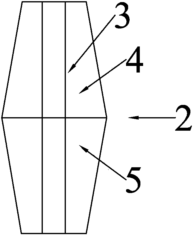
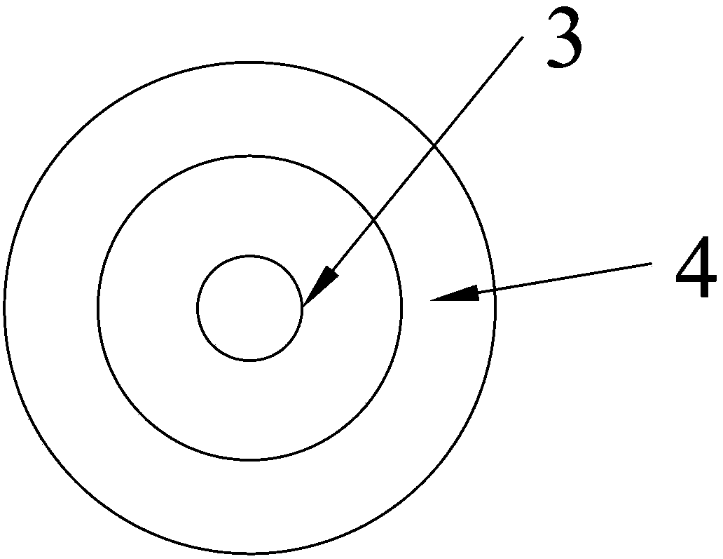
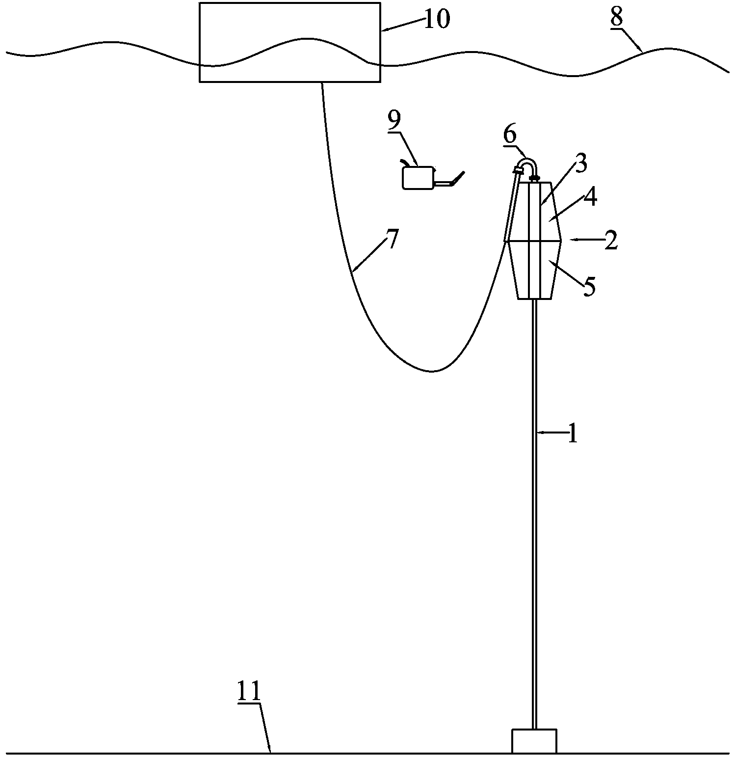
[0024] image 3 Shown is the overall schematic diagram of the free-standing riser based on the diving buoyancy cylinder 2, with the rigid riser 1 as the main body, standing ...


PUM


Abstract

The invention discloses a diving buoyancy tube. The diving buoyancy tube comprises an upper part buoy and a lower part buoy, wherein the upper part buoy is in a shape of a round platform; the lower part buoy is in a shape of an inverted round platform; the bottom surface area of the upper part buoy is the same as the top surface area of the lower part buoy; the bottom surface of the upper part buoy is fixedly connected to the top surface of the lower part buoy so as to form a whole; central shafts of both the upper part buoy and the lower part buoy are in the same straight line. According to the invention, the upper part buoy and the lower part buoy adopt round platform structural designs, and a traditional cylindrical buoyancy tube is designed to be drum-shaped, so that a three-dimensional effect of the streaming on the diving buoyancy tube is enhanced, eddy flaking off of a wake field is effectively inhibited, and a better water dynamic stability is provided; a gooseneck elbow device is installed on the outer edge of the diving buoyancy tube, so that the installation process of a flexible cross-over tube is simplified, and the risk of the collision of an ROV and the buoyancy tube is reduced.

Description

technical field [0001] The invention relates to the field of marine engineering equipment, in particular to a diving buoyancy cylinder. Background technique [0002] The free-standing riser is a new type of hybrid riser, which has been widely used in deepwater and ultra-deepwater oil and gas field development projects. A typical free-standing riser system uses a rigid riser as the main body, which stands vertically through the top tension of the submersible buoyancy cylinder, and a jumper connects the floating production platform with the gooseneck bend device on the top of the rigid riser. [0003] The submersible buoyancy cylinder is usually located at a position 50-200 meters below the sea surface. Its main function is to provide a certain buoyancy and tension the rigid riser, thereby improving the dynamic response of the rigid riser, reducing the vortex-induced vibration of the rigid riser, and improving the rigidity. Fatigue life of the riser. [0004] The structure o...

Claims


Application Information

Patent Timeline
Patent Type & Authority Applications(China)
IPC IPC(8): E21B41/00
Inventor 黄一甄兴伟张崎王文华
Owner DALIAN UNIV OF TECH
Why Eureka
Try Eureka