
Buffering system for solving scarce drainage capability of central drainage ditch of tunnel and control method of buffering system

A buffer system and drainage capacity technology, applied in drainage, earthwork drilling, safety devices, etc., can solve the problems of facility use and driving safety safety hazards, failure to consider the drainage capacity of the central ditch, insufficient drainage capacity of the central ditch, etc. Achieve the effect of making up for the lack of drainage capacity, ensuring maximum utilization, and saving costs

Inactive Publication Date: 2013-11-20
SOUTHWEST JIAOTONG UNIV
View PDF4 Cites 0 Cited by
  • Summary
  • Abstract
  • Description
  • Claims
  • Application Information

AI Technical Summary

Problems solved by technology

[0004] However, during the actual operation of the tunnel, affected by the increase in the duration and intensity of the rainfall, the conventional water inflow of the tunnel will increase to a certain extent, resulting in insufficient drainage capacity of the central ditch. When the tunnel water overflows through the central ditch to the tunnel surface, this It brings certain safety hazards to the use of various facilities in the tunnel and driving safety
In the existing tunnel design, the insufficient drainage capacity of the central ditch due to the increase of the conventional water inflow of the tunnel has not been taken into account

Method used


Image

  • Buffering system for solving scarce drainage capability of central drainage ditch of tunnel and control method of buffering system
  • Buffering system for solving scarce drainage capability of central drainage ditch of tunnel and control method of buffering system

Examples


Embodiment Construction

[0025] Below in conjunction with accompanying drawing, the present invention is described in further detail:

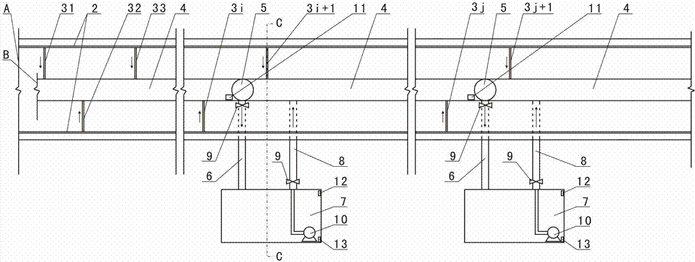
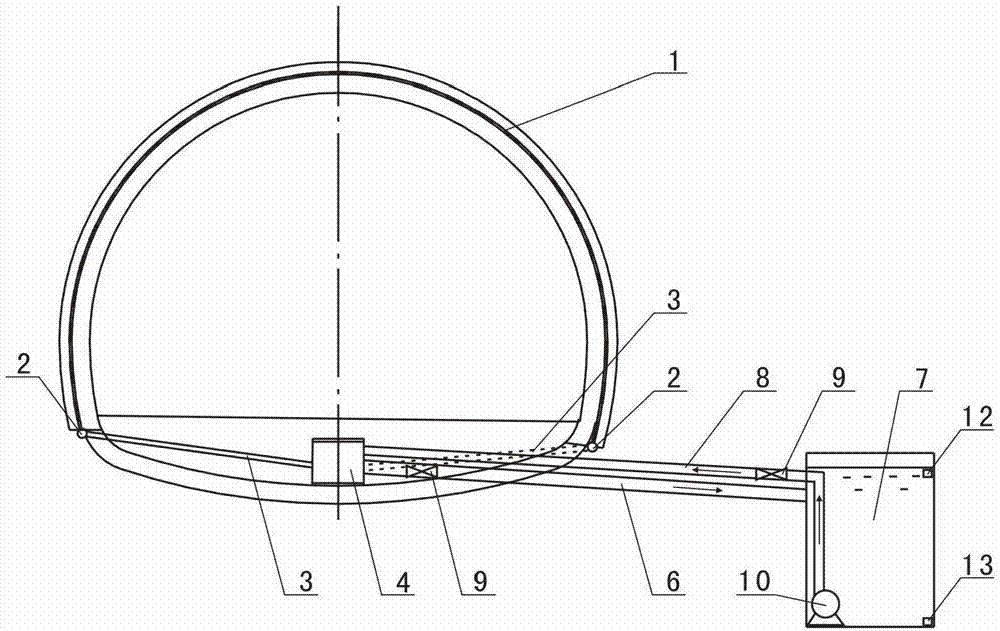
[0026] Such as figure 1 and figure 2 As shown, the buffer system of the present invention is applied to the tunnel drainage system. In the tunnel drainage system, the circular drainage blind pipe 1 discharges water into the longitudinal drainage pipe 2, and the water in the longitudinal drainage pipe 2 flows into the horizontal drainage pipe 3 in sequence ( Including the horizontal drainage pipes 31, 32, 33...3i, 3i+1...3j, 3j+1...), the flow of the horizontal drainage pipes 3 flows into the central ditch 4 in turn, and the water in the central ditch 4 is discharged to the outside of the tunnel. 4 in the direction of the centerline ( figure 1 The left and right direction in the center) is the vertical direction, and the two sides of the central ditch 4 are respectively provided with longitudinal drainage pipes 2, and the central ditch 4 and the longitudinal drainag...


PUM


Abstract

The invention discloses a buffering system for solving scarce drainage capability of a central drainage ditch of a tunnel. A central line of the central drainage ditch is taken as the longitudinal direction, a plurality of longitudinally arranged overflow wells are formed at edges of the central drainage ditch, buffering ponds are formed at positions, corresponding to the overflow wells, of the outer sides of the tunnel, the overflow wells are communicated with the buffering ponds via overflow pipes, the buffering ponds are connected with the central drainage ditch via drainage pipes, drainage pumps are mounted in the buffering ponds, and a water outlet of each drainage pump is connected with a water inlet of the corresponding drainage pipe. The invention further discloses a control method of the buffering system. According to water levels, in the central drainage ditch, at the positions of the overflow wells, valves on overflow valves are turned off or turned on, and valves on the drainage pumps and the drainage pipes are turned on or turned off at the same time to keep water volume in the central drainage ditch to be within the maximal flow value of the central drainage ditch. By the aid of a temporary water storage function of the buffering ponds, time-sharing distribution of the water volume in the central drainage ditch can be realized, the central drainage ditch is ensured to drain away water smoothly, and safety of the tunnel is facilitated.

Description

technical field [0001] The invention relates to an auxiliary drainage system in a tunnel, in particular to a buffer system and a control method for solving the insufficient drainage capacity of the central ditch of the tunnel. Background technique [0002] Since the tunnel is built under the surface, the groundwater in the stratum erodes the tunnel all the time, causing water leakage in the tunnel. The water leakage in the tunnel not only greatly reduces the service life and functions of various facilities in the tunnel, but also affects the safe driving of the tunnel. In order to ensure the safety and normal operation of the tunnel, it is necessary to do a good job in waterproofing and drainage of the tunnel. [0003] In the drainage design of existing tunnels, a system consisting of circular drainage blind pipes, longitudinal drainage pipes, horizontal drainage pipes, and central drainage ditch (hereinafter referred to as the central ditch) is used to solve the tunnel drai...

Claims


Application Information

Patent Timeline
IPC IPC(8): E21F16/02
Inventor 方勇曹礼聪周超月符亚鹏彭佩杨斌
Owner SOUTHWEST JIAOTONG UNIV
Learn More