Water pond filter pump with high efficiency and low cost

A low-cost, high-efficiency technology, applied to the components, pumps, pump elements, etc. of the pumping device for elastic fluids, which can solve the problem of low efficiency, low flow rate of the pool filter pump, clockwise rotation and counterclockwise rotation, etc. problems, to achieve the effect of reducing manufacturing costs, reducing assembly links, and improving water efficiency

Active Publication Date: 2013-11-20
SHANGHAI JILONG SPORT & LEISURE PROD CO LTD
View PDF8 Cites 2 Cited by
  • Summary
  • Abstract
  • Description
  • Claims
  • Application Information

AI Technical Summary

Problems solved by technology

When working, after the water flow enters the impeller cavity from the water inlet pipe, under the guidance of the rotating impeller, the direction of the water flow forms a 90° angle with the outlet pipe, which is not conducive to the smooth discharge of water, and there are problems of small flow, low pressure and low efficiency.
[0003] In order to solve the problems of small flow rate, low pressure and low efficiency of the pool filter pump, the patent document with the authorized announcement number CN2541640Y discloses a pool filter pump, such as figure 2 As shown, by designing an outer arched arc-shaped structure at the connection between the outlet pipe port and the impeller cavity and designing the impeller as a centrifugal type, the problems of small flow, low pressure, and low efficiency are solved to a certain extent.
However, the motor type of the pool filter pump is generally a single-phase AC permanent magnet synchronous motor. The working principle of this motor is: when the power is turned on, the stator coil generates a pulsating magnetic field, which can be decomposed into two rotating magnetic fields, positive and negative. Therefore, the motor may rotate clockwise or counterclockwise in a steady state, so the direction of rotation is uncertain after each start
Therefore, the centrifugal arrangement of the outlet pipe and the impeller cavity will lead to the following situations: when the impeller starts clockwise, the flow is normal; when the impeller starts counterclockwise, the water is difficult to press out from the outlet pipe, so the flow is very Small, there are still problems of small flow, low pressure and low efficiency
[0004] In addition, the structure of the pool filter pump currently on the market generally has the phenomenon that the protection design is not considered comprehensively, which is likely to bring harm to consumers; at the same time, there are too many structural parts and too many connections during design, resulting in high manufacturing costs and poor quality. Stablize

Method used


Image

  • Water pond filter pump with high efficiency and low cost
  • Water pond filter pump with high efficiency and low cost
  • Water pond filter pump with high efficiency and low cost

Examples


Embodiment Construction

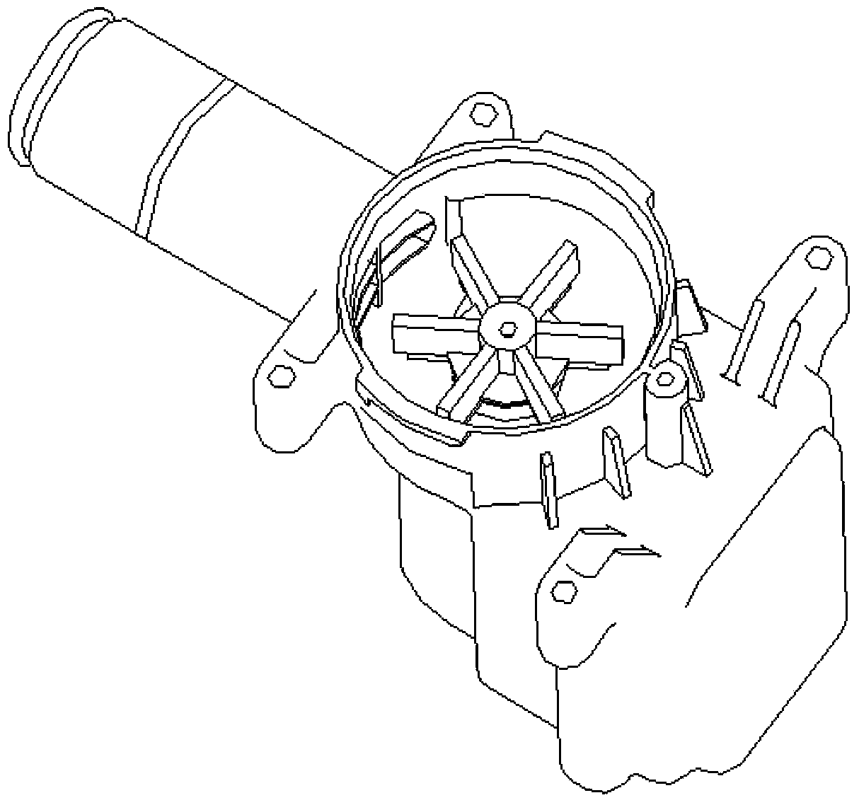
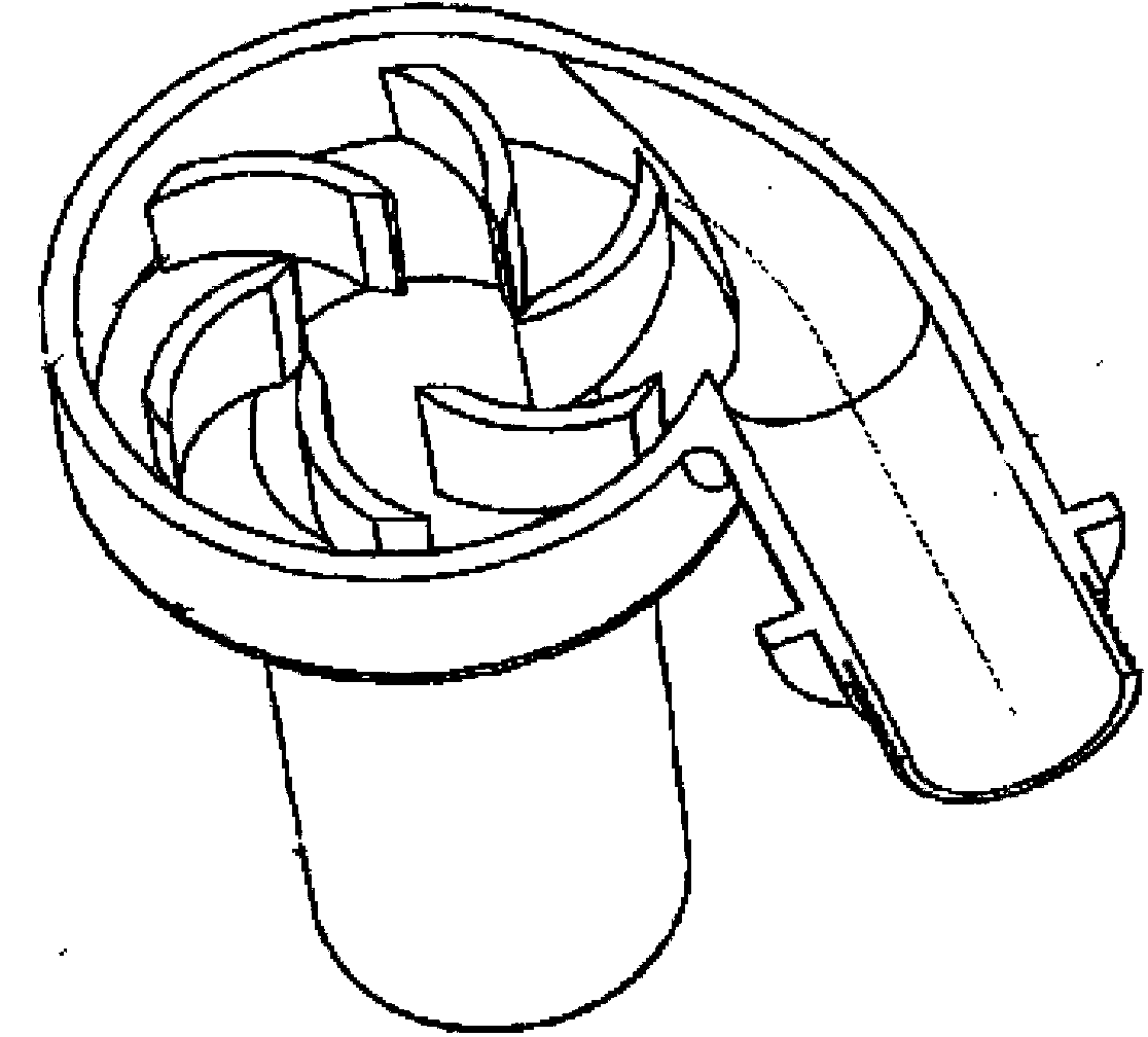
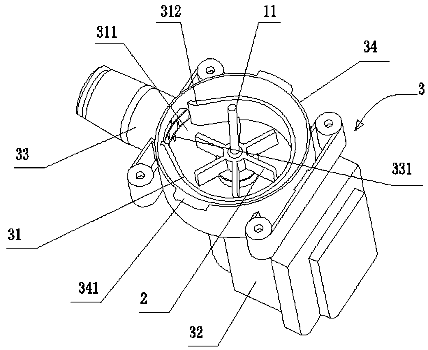
[0026] like image 3 , Figure 4 , Figure 5 , Image 6 and Figure 7 As shown, a high-efficiency and low-cost pool filter pump includes a motor 1, an impeller 2 and a motor housing 3, the impeller is sleeved on the rotor shaft 11 of the motor, and the motor housing includes a housing for the impeller. The annular impeller cavity 31 and the pump body 32 for accommodating the motor, a gap 311 is formed on one side of the impeller cavity, and the impeller cavity on both sides of the gap extends outwards to form an arc-shaped structure 312, the A water outlet pipe 33 is provided at the gap, and the water outlet pipe communicates with the impeller cavity through the gap. In this way, the connection between the impeller cavity and the outlet pipe is two outwardly extending arc structures, that is, compared with the impeller cavity, the position of the outlet pipe extends outward for a certain distance, through the above-mentioned double arc structure design of the impeller cavi...


PUM


Abstract

The invention discloses a water pond filter pump with high efficiency and low cost, which comprises a motor, an impeller and a motor shell, wherein the impeller is arranged on a rotor spindle of the motor in a sleeving manner; the motor shell comprises an annular impeller cavity for accommodating the impeller and a pump body for accommodating the motor; a notch is formed in one side of the impeller cavity; the parts, on two sides of the notch, of the impeller cavity extend outwards to form arc structures; a water discharge pipe is arranged at the notch, and is communicated with the impeller cavity via the notch. With adoption of the water pond filter pump, the high flow rate can be acquired at lower power, the water discharge efficiency is improved, the assembling links for parts are reduced, the manufacturing cost is lowered, the product quality is improved, and the use safety for a user is improved.

Description

technical field [0001] The invention relates to a pool filter pump, in particular to a pool filter pump with high efficiency and low cost. Background technique [0002] Domestic pools, baths and swimming pools, hereinafter collectively referred to as pools, have been generally recognized and accepted by society because of their multiple functions such as bathing and leisure. Each pool is equipped with a pool filter pump to realize the function of pumping and filtering. The pool filter pump mainly includes a casing and a filter chamber, a filter element, a motor, and an impeller arranged in the casing. The motor and the impeller are usually arranged in the motor casing. The motor casing includes the impeller chamber for housing the impeller and the pump body for housing the motor. The impeller chamber is connected to the water outlet pipe and the water inlet pipe. It is: the circular impeller cavity is connected to the outlet pipe, such as figure 1 shown. When working, aft...

Claims


Application Information

Patent Timeline
Patent Type & Authority Applications(China)
IPC IPC(8): F04D29/40F04D29/70
Inventor 吴敏华饶厚熙梅安平朱冬冬
Owner SHANGHAI JILONG SPORT & LEISURE PROD CO LTD
Why Eureka
Try Eureka