
Motor combined hermetically-sealed structure

A sealed structure and combined technology, applied in the direction of electric components, electrical components, electromechanical devices, etc., can solve the problems of motor failure, shortened life of seals, and easy water ingress of the motor, so as to achieve convenient installation and replacement, prolong service life, Enhanced sealing performance

Inactive Publication Date: 2013-11-20
DONGFANG ELECTRIC CORPLESHAN NEW ENERGY EQUIP
View PDF3 Cites 5 Cited by
  • Summary
  • Abstract
  • Description
  • Claims
  • Application Information

AI Technical Summary

Problems solved by technology

[0002] The direct drive motor of new energy electric vehicles is directly placed at the bottom of the vehicle and connected to the drive shaft. The working environment of the motor is harsh and it is easily affected by water, mud and sand.
If the front end bearing of the motor is not properly protected, it is very easy to cause damage to the bearing, which in turn leads to motor failure
In addition, due to the low position of the motor, it is easy to be soaked in water, which will also damage the motor and affect the operation of the vehicle.
Since the motor shaft is a rotating part, it is difficult to ensure the waterproofness of the shaft penetration. The motor is prone to water ingress and even burns, which will affect the service life of the motor.
Existing motor seal structures mostly use skeleton seals, but the seals are easily affected by the environment, the life of the seals is shortened, and the motor shaft is easy to wear, so the motor needs frequent maintenance, which cannot meet the use requirements

Method used


Image

  • Motor combined hermetically-sealed structure

Examples


Embodiment Construction

[0011] The present invention will be further described below in conjunction with accompanying drawing, protection scope of the present invention is not limited to the following:

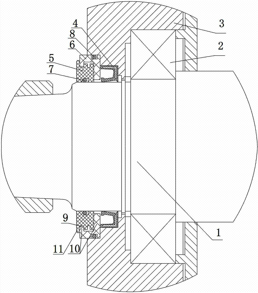
[0012] Such as figure 1 As shown, the combined sealing structure of the motor includes the shaft extension end 1 and the end cover 3 of the rotor. The shaft extension end 1 is installed on the end cover 3 through the bearing 2, and a skeleton seal is arranged between the end cover 3 and the shaft extension end 1. 4. A dynamic seal is provided between the axially outer end cover 3 of the skeleton seal 4 and the shaft extension end 1, and the dynamic seal includes a dynamic seal ring 5 arranged on the side of the shaft extension end 1 and a dynamic seal ring 5 arranged on the end cover 3 The static sealing ring 6 on the side, the O-ring A7 is set between the dynamic sealing ring 5 and the shaft extension end 1, the O-ring B8 is set between the static sealing ring 6 and the end cover 3, the dynamic seal...


PUM


Abstract

The invention discloses a motor combined hermetically-sealed structure. The structure comprises a shaft extension end (1) and an end cover (3) of a rotor, wherein a reinforced seal (4) is arranged between the end cover (3) and the shaft extension end (1); a movable seal is arranged between the end cover (3) at the axial outer side of the reinforced seal (4) and the shaft extension end (1); the movable seal comprises a movable sealing ring (5) which is arranged on the side of the shaft extension end (1) and a static sealing ring (6) which is arranged on the side of the end cover (3); an axial labyrinth sealing structure is arranged on the contact part of the movable sealing ring (5) and the static sealing ring (6). The motor combined hermetically-sealed structure has the beneficial effects that the motor combined hermetically-sealed structure is simple in structure, convenient to install and change and reasonable in design; and a combined waterproof structure of a non-contact type movable seal and a contact type static seal is adopted, water, mud and sand can be effectively prevented from entering a motor, the reinforced seal is slightly influenced, accordingly, the sealing performance of the reinforced seal is improved, the service life of the reinforced seal is prolonged, and the structure is reliable in performance.

Description

technical field [0001] The invention relates to the technical field of motor sealing, in particular to a combined motor sealing structure. Background technique [0002] The direct drive motor of new energy electric vehicles is directly placed at the bottom of the vehicle and connected to the drive shaft. The working environment of the motor is harsh and it is easily affected by water, mud and sand. If the front end bearing of the motor is not properly protected, it is very easy to cause damage to the bearing, which in turn leads to motor failure. In addition, due to the low position of the motor, it is easy to be soaked in water, which will also damage the motor and affect the operation of the vehicle. Since the motor shaft is a rotating part, it is difficult to ensure the waterproofness of the shaft penetration, and the motor is prone to water ingress and even burnt, which affects the service life of the motor. The existing motor sealing structure mostly adopts skeleton s...

Claims


Application Information

Patent Timeline
Patent Type & Authority Applications(China)
IPC IPC(8): H02K5/10
Inventor 孙树林应青陶浩钟伟李立安
Owner DONGFANG ELECTRIC CORPLESHAN NEW ENERGY EQUIP
Learn More