Switchgear for high voltage circuits

A high-voltage circuit and switchgear technology, applied in the field of switches, can solve problems such as partial discharge

Active Publication Date: 2017-01-25
NORTH CHINA ELECTRIC POWER UNIV (BAODING)
View PDF7 Cites 0 Cited by
  • Summary
  • Abstract
  • Description
  • Claims
  • Application Information

AI Technical Summary

Problems solved by technology

[0005] The main purpose of the present invention is to provide a switchgear without partial discharge, so as to solve the problem of partial discharge in the related art when the switch controls the high-voltage power transmission system to conduct safe conduction and disconnection operations

Method used


Image

  • Switchgear for high voltage circuits
  • Switchgear for high voltage circuits
  • Switchgear for high voltage circuits

Examples


Embodiment Construction

[0022] It should be noted that the embodiments in the present application and the features of the embodiments may be combined with each other in the case of no conflict. The present invention will be described in detail below with reference to the accompanying drawings and in conjunction with the embodiments.

[0023] Embodiments of the present invention provide a switch device for a high-voltage circuit, which is used to control the on and off of the high-voltage circuit.

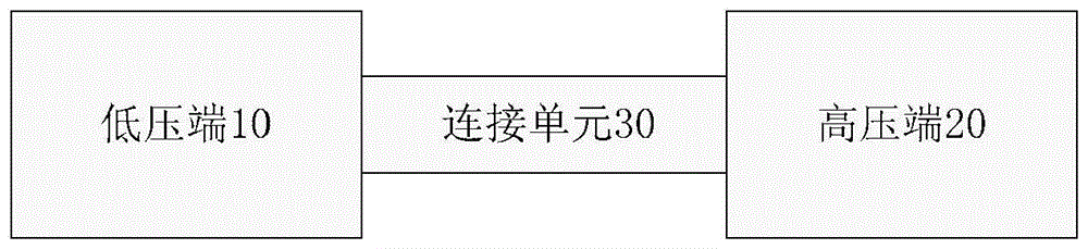
[0024] figure 1 is a schematic diagram of a switchgear for a high-voltage circuit according to an embodiment of the present invention.

[0025] like figure 1 As shown, the device includes a low pressure end 10 , a high pressure end 20 and a connection unit 30 , and the low pressure end 10 is connected to the high pressure end 20 through the connection unit 30 .

[0026] The low-voltage terminal 10 is connected to the low-voltage circuit and can be used for receiving control signals from the low-voltage ...


PUM


Abstract

The invention discloses a switching device for a high voltage loop. The switching device for the high voltage loop comprises a low voltage end, a high voltage end and a connection unit, wherein the low voltage end is connected to a low voltage loop and is used for receiving a control signal from the low voltage loop; the high voltage loop is switched off or conducted under the control of the control signal; the high voltage end comprises a high voltage end cavity; a gap in the high voltage end cavity is totally filled with a solid insulated filler; the connection unit comprises a first end and a second end; the first end is connected to the low voltage end; the second end is connected to the high voltage end. By the switching device, partial discharge cannot be generated when a switch controls a high voltage power transmission system to carry out safe conduction and switching-off operations.

Description

technical field [0001] The present invention relates to the field of switches, in particular, to a switch device for a high-voltage circuit. Background technique [0002] With the increasing demand for electric power in society, the electric power industry has developed rapidly. The development speed of the electric power industry is restricted by the safety of the transmission system. Therefore, the safe operation of the transmission system has become a major concern of the electric power industry. In order to ensure the safe operation of the power transmission system, the power industry generally conducts regular inspections on power facilities such as the power transmission system. During the detection process, it is often necessary to perform disconnection and turn-on operations on the power transmission system. Since the power transmission system is generally a high-voltage circuit, its on and off operations pose a huge threat to the safety of people and equipment. ...

Claims


Application Information

Patent Timeline
Patent Type & Authority Patents(China)
IPC IPC(8): H03K17/567
Inventor 马国明李成榕江军罗定平李庆民
Owner NORTH CHINA ELECTRIC POWER UNIV (BAODING)
Why Eureka
Try Eureka