
Screen printing device and screen printing method

A screen printing device and screen printing technology, applied in screen printing, screen printing machines, printing devices, etc., can solve problems such as uneven filling properties, and achieve the effect of ensuring filling properties and good filling properties

Active Publication Date: 2013-11-20
PANASONIC CORP
View PDF8 Cites 3 Cited by
  • Summary
  • Abstract
  • Description
  • Claims
  • Application Information

AI Technical Summary

Problems solved by technology

[0005] However, although the above-mentioned closed-type squeegee coating mechanism generally has good filling performance, it may not always be possible to ensure the necessary filling performance when it is targeted at materials that are more difficult to print, such as when it is targeted at a mesh mask with a fine grid pattern. fully filling case

Method used


Image

  • Screen printing device and screen printing method
  • Screen printing device and screen printing method
  • Screen printing device and screen printing method

Examples


Embodiment Construction

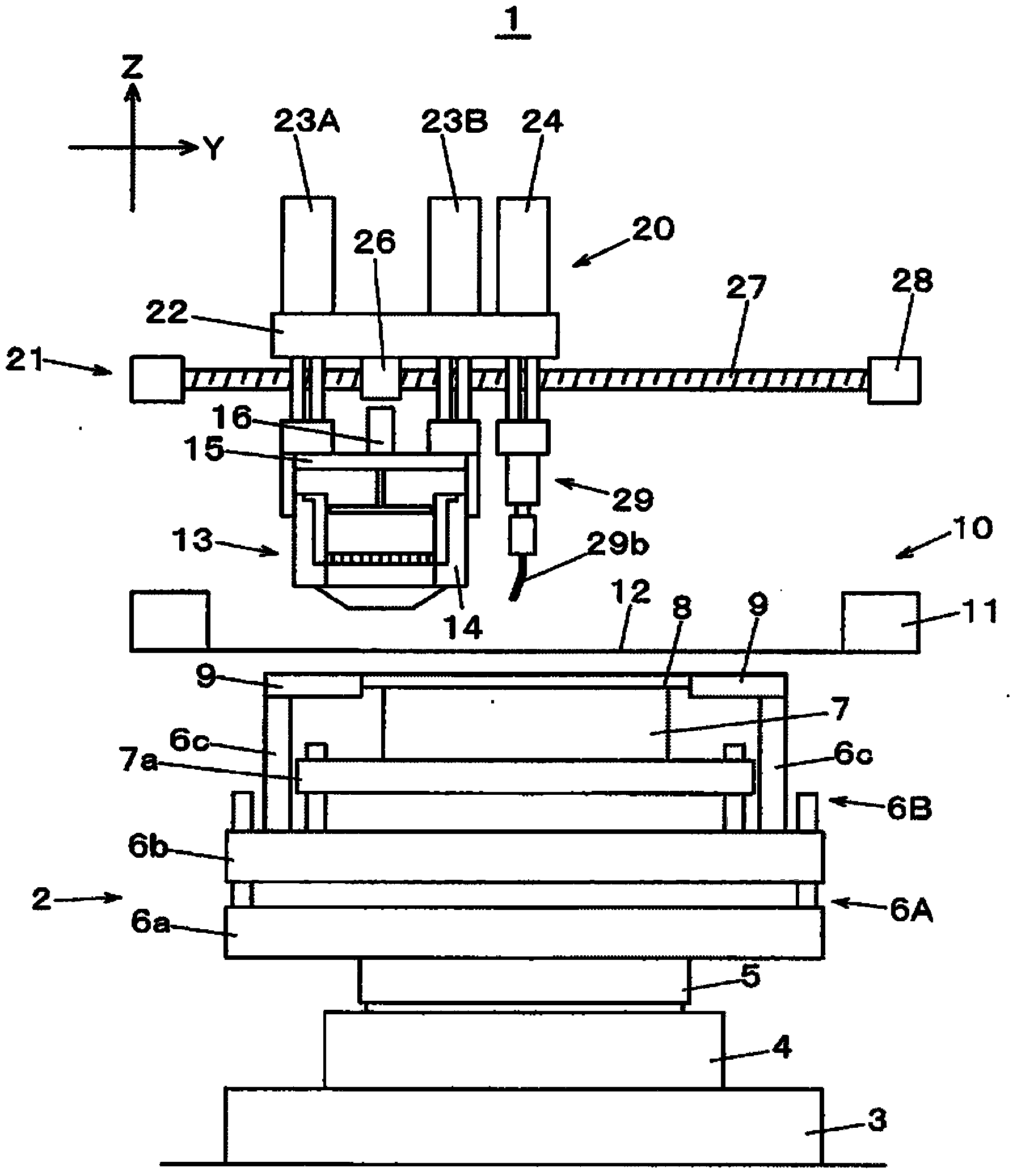
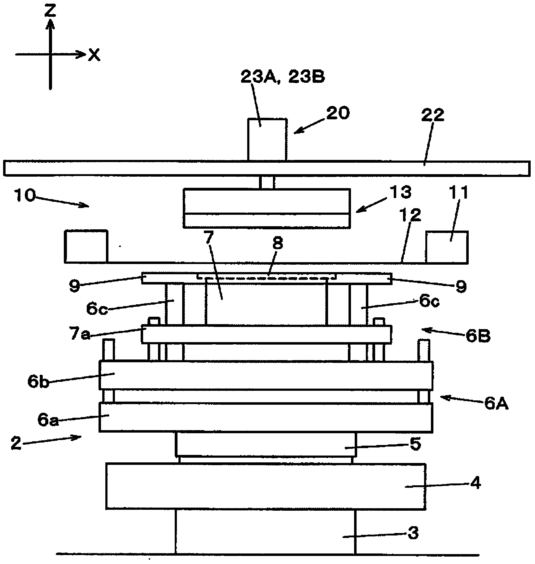
[0038] Next, embodiments of the present invention will be described with reference to the drawings. First, refer to figure 1 The structure of the screen printing device 1 will be described. This screen printing device 1 has a function of printing a soldering or circuit on a substrate through a pattern hole by performing a squeegee operation in which the squeegee unit comes into contact with the upper surface of a mesh mask with a pattern hole and slides in the squeegee direction. The function of the paste used for forming.

[0039] exist figure 1 , figure 2 Among them, a screen printing unit 10 is disposed above the substrate positioning unit 2 of the screen printing device 1 . The substrate positioning unit 2 is configured such that a θ-axis table 5 is stacked on a movable table composed of a Y-axis table 3 and an X-axis table 4 , and a first Z-axis table is arranged on the θ-axis table 5 6A, the second Z-axis table 6B, and the substrate lower support portion 7 is dispo...


PUM


Abstract

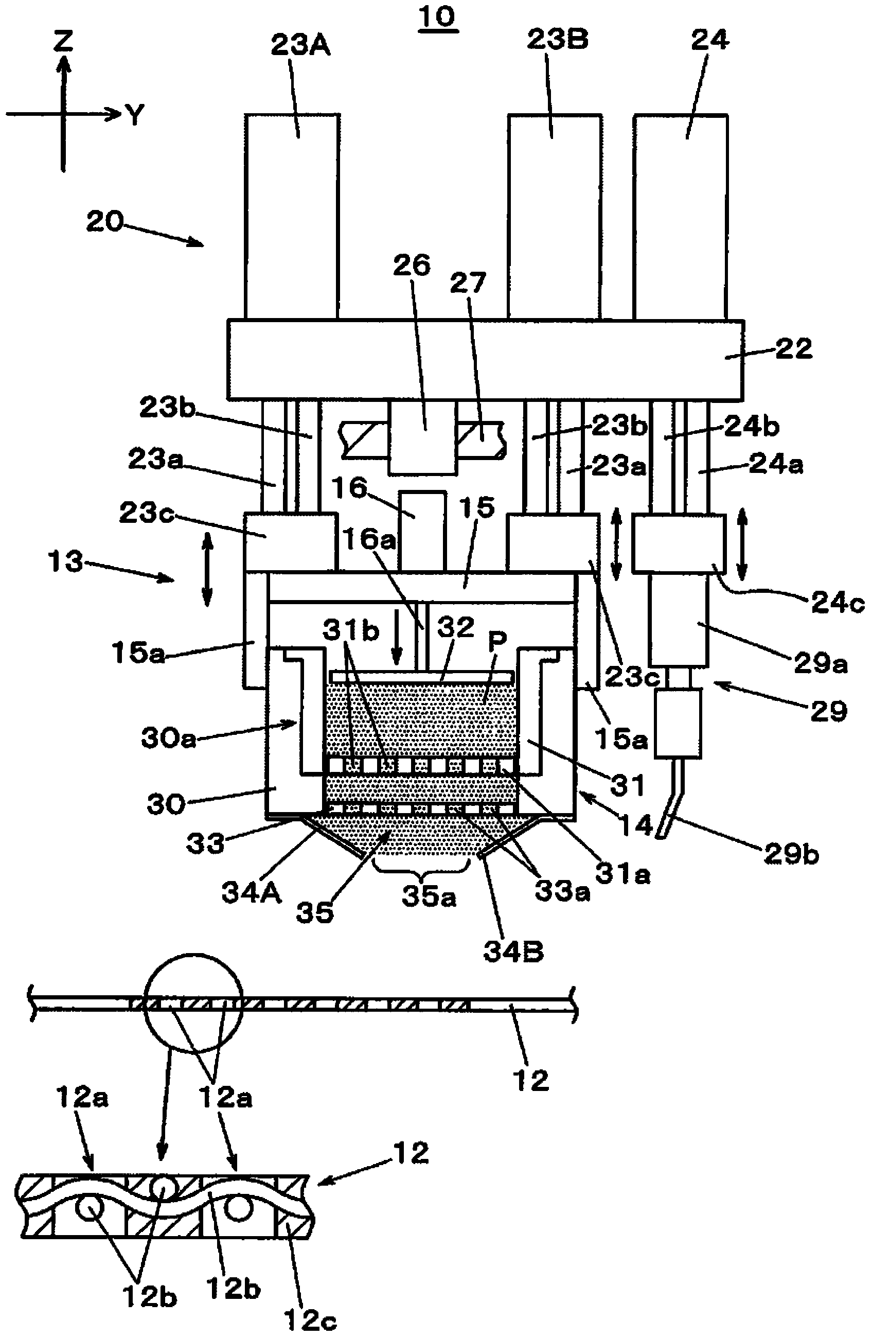
In the present invention, in a screening operation by a closed squeegee mechanism (13) having therewithin the configuration of a compressed paste (P) filling from a printing aperture (35a) between a pair of sliding members (34A, 34B): before the filling of the paste into pattern holes (12a) via the printing aperture (35a), the sliding member (34B) positioned on the front side in the direction of squeegeeing of the pair of sliding members (34A, 34B) is moved in the squeegeeing direction, by which means the paste (P) supplied to the outside of the closed squeegee mechanism (13) at the upper surface of a mesh mask (12) fills the inside of the pattern holes (12a).

Description

technical field [0001] The present invention relates to a screen printing device and a screen printing method for printing paste on a substrate for component joining or circuit formation. Background technique [0002] Screen printing is known as a method of supplying a paste for joining components, forming a circuit, or the like to a substrate. In this method, a screen printing device is used, which is equipped with a device for printing paste on the electrode surface of the substrate through pattern holes provided in the screen mask and bringing the substrate into contact with the lower surface of the screen mask. A screen printing mechanism that slides a squeegee coating unit on the screen mask in a state (for example, Patent Document 1). [0003] In the example shown in this patent document 1, as the squeegee unit, there is shown an example using a closed type squeegee mechanism configured as follows, that is, a paste box storing paste is installed inside, and the paste ...

Claims


Application Information

Patent Timeline
IPC IPC(8): B41F15/42B41F15/08H05K3/34
CPCB41P2215/132H05K3/3484B41F15/08H05K3/12B41M1/12B41F15/0881H05K2203/0139B41F15/36H05K3/1233B41F15/44B41F15/42B41F15/26B41F15/423B41F15/46H01L31/18H05K3/3485B41F15/085
Inventor 田中哲矢大武裕治
Owner PANASONIC CORP
Learn More