Gas generator
A technology of gas generators and gas generating agents, applied in the direction of gas generating devices, compressed gas generation, chemical instruments and methods, etc., to achieve the effects of less constraints, safe manufacturing, and cost reduction
- Summary
- Abstract
- Description
- Claims
- Application Information
AI Technical Summary
Problems solved by technology
Method used
Image

Examples
Embodiment approach 1
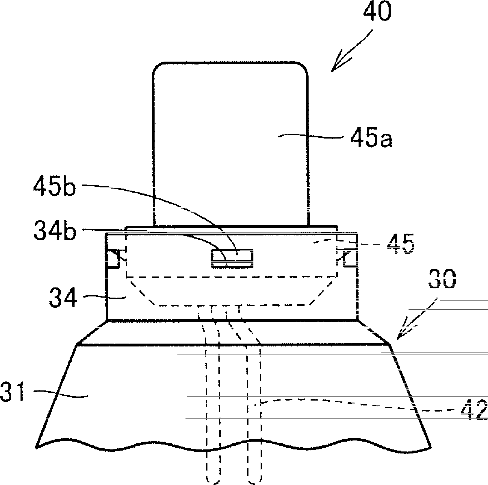
[0060] figure 1 It is a schematic diagram of the gas generator in Embodiment 1 of this invention. First, refer to the figure 1 , the overall structure of the gas generator 1A of this embodiment will be described.
[0061] Such as figure 1 As shown, the gas generator 1A of this embodiment has a short cylindrical casing with both ends in the axial direction closed, and the holding part 30, the igniter 40, and the gas generator are housed in the casing as components. agent 61, filter 70 and the like. The short cylindrical casing includes a lower side shell 10 and an upper side shell 20 . Each of the lower side shell 10 and the upper side shell 20 is composed of a press-formed product formed by press-working a single metal plate-shaped member.
[0062] The lower side shell 10 and the upper side shell 20 are respectively formed in a bottomed cylindrical shape, and these open surfaces are combined and joined to face each other to constitute an outer shell portion of the housing...
Embodiment approach 2
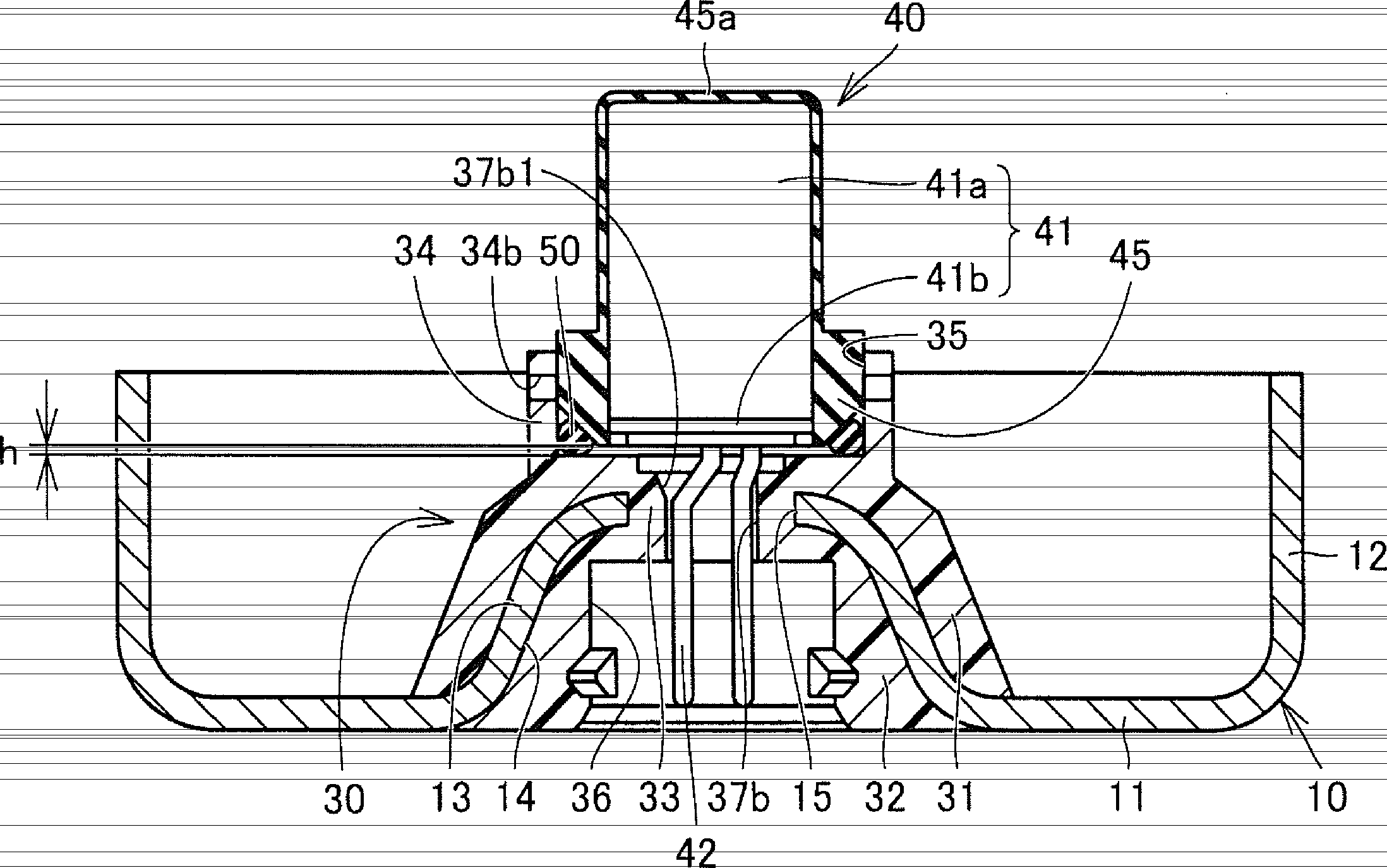
[0115] Figure 7 It is a schematic diagram of the gas generator in Embodiment 2 of this invention. also, Figure 8A It is a plan view of the holding part of the gas generator of this embodiment, Figure 8B is the bottom view of the igniter. Below, refer to these Figure 7 , Figure 8A and Figure 8B , the configuration of the gas generator 1B of this embodiment will be described.
[0116] Such as Figure 7 As shown, the gas generator 1B of this embodiment differs from the gas generator 1A of Embodiment 1 of the present invention described above in the shape of the connecting portion 33 of the holding portion 30 . Specifically, in the gas generator 1B of the present embodiment, the insertion hole 38 provided in the connecting portion 33 does not have a shape corresponding to the shape of the pair of terminal pins 42 of the igniter 40, but is viewed from a larger plan view. Consists of a single hole in a perfect circle shape. Therefore, the insertion hole 38 does not fu...
Embodiment approach 3
[0123] Figure 10 It is a schematic diagram of the gas generator in Embodiment 3 of this invention. Below, refer to the Figure 10 , the configuration of the gas generator 1C of this embodiment will be described.
[0124] Such as Figure 10 As shown, the gas generator 1C of the present embodiment is different from the gas generator 1A of the first embodiment of the present invention described above in the surface shape of the protruding cylindrical portion 13 provided on the lower side shell 10 . Specifically, in the gas generator 1C of the present embodiment, a plurality of recesses 16 are provided on the surface of the protruding cylindrical portion 13 on the combustion chamber 60 side.
[0125] The plurality of recesses 16 are in a shape that does not continuously surround the protruding cylindrical portion 13 at least along the circumferential direction (that is, not in the shape of an annular groove). It is formed by setting marks on the surface after processing. In ...
PUM
 Abstract
Description
Claims
Application Information
 - R&D Engineer
- R&D Manager
- IP Professional
- Industry Leading Data Capabilities
- Powerful AI technology
- Patent DNA Extraction
Browse by: Latest US Patents, China's latest patents, Technical Efficacy Thesaurus, Application Domain, Technology Topic.
© 2024 PatSnap. All rights reserved.Legal|Privacy policy|Modern Slavery Act Transparency Statement|Sitemap