Self-alignment shaft head clamping mechanism

A technology of clamping mechanism and positive shaft, which is applied in the direction of metal rolling stand, metal rolling mill stand, metal rolling, etc. It can solve the problem of difficult adjustment of the position of the shaft head of the supporting plate and the universal coupling, and the in-out shaft of the work roll. The problems such as head difficulty can be solved to achieve the effect of flexible and effective adjustment, saving the time of changing rolls and eliminating installation errors

Active Publication Date: 2013-11-27
CHINA NAT HEAVY MACHINERY RES INSTCO
View PDF5 Cites 1 Cited by
  • Summary
  • Abstract
  • Description
  • Claims
  • Application Information

AI Technical Summary

Problems solved by technology

[0003] In order to overcome the above-mentioned problems in the prior art that the work rolls are difficult to enter and exit the shaft head, and the position of the shaft head of the supporting plate and the uni

Method used


Image

  • Self-alignment shaft head clamping mechanism
  • Self-alignment shaft head clamping mechanism
  • Self-alignment shaft head clamping mechanism

Examples


Example Embodiment

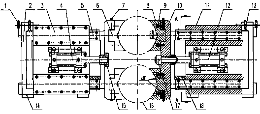
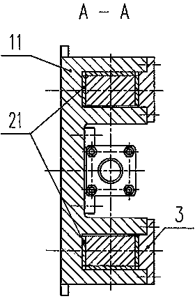
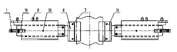
[0020] The structural principle and working principle of the present invention will be described in detail below in conjunction with the accompanying drawings.

[0021] Reference figure 1 , figure 2 , image 3 , Figure 4 , A self-aligning shaft clamping mechanism, the standard oil cylinder 4 is fixed on the left fixed block 2 and is threadedly connected with the left bracket 5. The left bracket 5 extends parallel to the two sides of the standard oil cylinder 4 on the left The fixed block 2 is in the groove and is in sliding contact with the left fixed block 2. The adjustment oil cylinder 12 is fixed on the right fixing block 11 and is screwed to the right bracket 10. The part of the right bracket 10 extending parallel to both sides of the adjustment oil cylinder 12 is located in the groove of the right fixing block 11 and is fixed to the right Block 11 is in sliding contact. The standard oil cylinder 4 and the adjustment oil cylinder 12 are respectively connected with the lef...


PUM


Abstract

The invention relates to a self-alignment shaft head clamping mechanism. A standard oil cylinder is fixed on a left fixed block and is in threaded connection with a left bracket; the part of the left bracket, extending to two sides parallel to the standard oil cylinder, is positioned in a groove of the left fixed block and is in sliding contact with the left fixed block; an adjusting oil cylinder is fixed on a right fixed block and is in threaded connection with a right bracket; the part of the right bracket, extending to two sides parallel to the adjusting oil cylinder, is positioned in a groove of the right fixed block and is in sliding contact with the right fixed block; support plates are arranged between the left bracket and a longitudinally distributed universal coupling shaft head and between the right bracket and the other longitudinally distributed universal coupling shaft head and are in threaded connection with the left bracket and the right bracket respectively; the contact surfaces between the support plates and the universal coupling shaft heads are arc surfaces with the same diameter, and the contact surfaces a and b between the supporting plates and the corresponding brackets are arc-shaped along the axis direction of the universal coupling shaft heads. The self-alignment shaft head clamping mechanism has the characteristics of being convenient to operate, flexible in adjustment, and capable of saving roller replacement time and auxiliary rolling time.

Description

technical field [0001] The invention relates to a metallurgical plate and strip rolling equipment, in particular to a self-aligning shaft head clamping mechanism. Background technique [0002] In order to save the time of changing rolls and improve the productivity of the strip, the shaft head clamping device is widely used in the strip rolling mill. The shaft head clamping device is driven by the oil cylinder to slide the left and right brackets to slide in the fixed block, and the shaft head of the universal coupling is embraced by the supporting plate on the bracket. The bracket and the pallet are joined together by bolts. In order to ensure the close contact between the bracket and the shaft head, the contact part of the shaft head of the pallet is arc-shaped, and the diameter is the same as that of the shaft head. When changing rolls, the shaft head clamping device holds the shaft head of the universal coupling tightly, and the flat head of the work roll performs a pu...

Claims


Application Information

Patent Timeline
IPC IPC(8): B21B31/08
Inventor 窦锋陈玺刘云飞
Owner CHINA NAT HEAVY MACHINERY RES INSTCO
Why Eureka
Try Eureka