Compressor welding tool

A technology for welding tooling and compressors, which is applied in welding equipment, auxiliary welding equipment, welding/cutting auxiliary equipment, etc., and can solve the problem of poor dimensional consistency and stability of scraper compressor components, unguaranteed welding quality, and impact on Solve problems such as welding production speed, achieve the effect of shortening tooling adjustment time, reducing blanking and scribing work, and improving welding speed

Active Publication Date: 2013-11-27
广西玉柴专用汽车有限公司
View PDF7 Cites 2 Cited by
  • Summary
  • Abstract
  • Description
  • Claims
  • Application Information

AI Technical Summary

Problems solved by technology

[0002] In the welding process production of the current scraper compressor, the man-hours required for welding are less, and more than 2 / 3 of the total processing man-hours are used for material preparation, assembly, scribing and other auxiliary work. Affects the production speed of welding. In addition, the locking support box, oil cylinder seat, and extrusion plate shaft seat in the parts to be welded have precise coaxiality requirements, which are prone to deviations and difficult to adjust. The size of the scraper compressor parts Poor consistency and stability, welding quality cannot be guaranteed

Method used


Image

  • Compressor welding tool
  • Compressor welding tool
  • Compressor welding tool

Examples


Embodiment 1

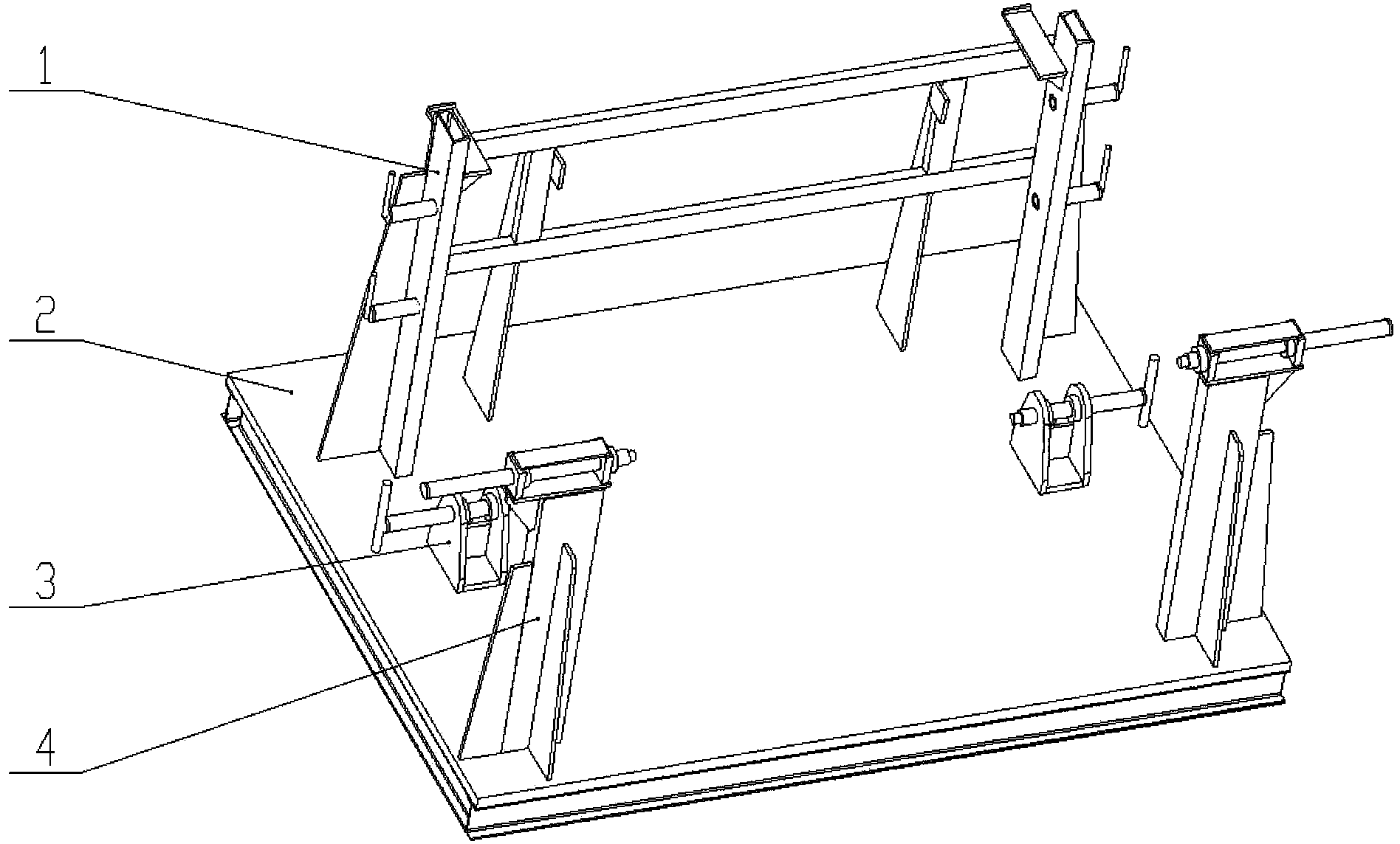
[0027] Such as figure 1 , figure 2 , image 3 , Figure 4 As shown in , a compressor welding tool, comprising: a locking support box positioning mold assembly 1 is fixed on one side of the base platform 2 close to the edge, and two adjustments are fixed on the other side of the base platform 2 close to the two corners. The connecting rod 9 is opposite to the extrusion plate shaft seat positioning die 4, and an adjusting screw 7 is fixed between the locking support box positioning die assembly 4 and the extrusion plate shaft seat positioning die 1 near the edge of the base platform 2 Direction is relative to extruding oil cylinder seat positioning mold 3.

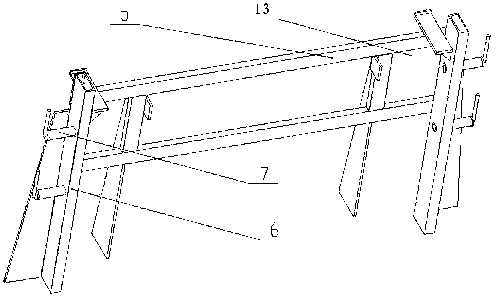
[0028] The positioning mold assembly 1 of the locking support box includes: a support connecting frame 5, an adjusting screw column 6, and an adjusting screw 7, and the horizontal ends of the supporting connecting frame 5 are fixed on one side of the adjusting screw column 6, and the adjusting screw column 6. The device...

Embodiment 2

[0034] see Figure 5 , the actual welding of the compressor:

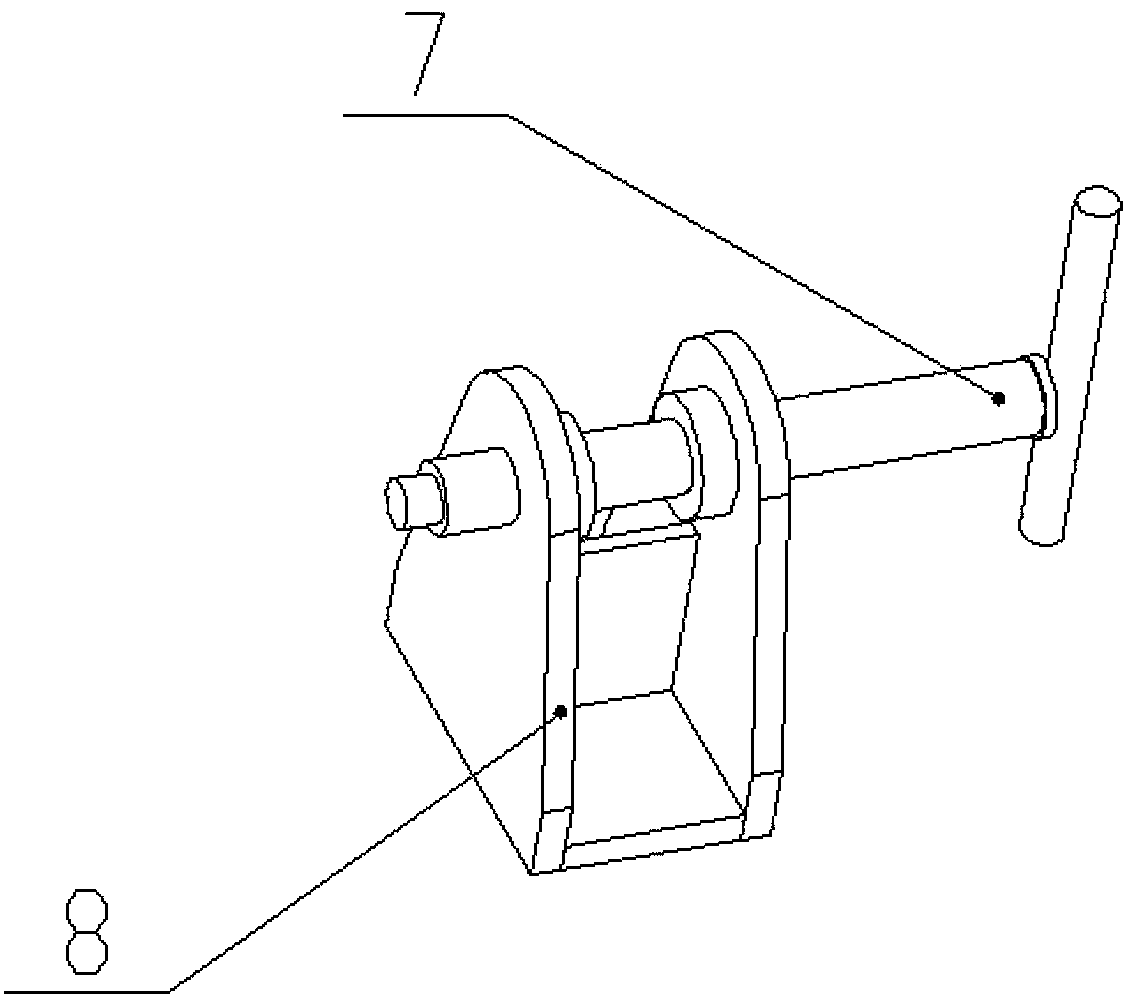
[0035] In the welding production of the compressor, when hoisting, use the fixing groove 13 of the locking support box positioning mold assembly 1 on the base platform 2 as a reference for positioning, and use its adjusting screw 7 to rotate and push to the compressor fixing seat for the first fulcrum Fixing and coaxiality adjustment, the second fulcrum positioning is performed by squeezing the U-shaped slot 8 of the positioning mold 3 of the cylinder seat, and the second fulcrum is fixed and coaxiality is fixed and coaxiality is carried out by setting the top adjusting screw 7 to rotate and push to the compressor fixing seat Adjustment, and then through the rotation of the adjustment connecting rod 9 of the positioning die 3 of the extrusion plate shaft seat, the third point is fixed and the coaxiality adjustment is carried out on the compressor fixed seat, and the six direction points are pressed and positioned, ...


PUM


Abstract

The invention relates to a compressor welding tool which comprises a locking and supporting box positioning die component, extruding plate rotating shaft seat positioning dies and extruding oil cylinder seat positioning dies. The locking and supporting box positioning die component is fixed on one side of a base platform, the extruding plate rotating shaft seat positioning dies are oppositely fixed on the other side of the base platform, and the extruding oil cylinder seat positioning dies opposite in direction are fixed on the base platform between the locking and supporting box positioning die component and the extruding plate rotating shaft seat positioning dies. The compressor welding tool has the advantages that to-be-welded components are enabled to be accurately positioned and reliably clamped, assembling and welding of a to-be-welded piece are facilitated, structural accuracy of the to-be-welded piece is improved, and the like.

Description

technical field [0001] The invention relates to the welding field, in particular to a compressor welding tool. Background technique [0002] In the welding process production of the current scraper compressor, the man-hours required for welding are less, and more than 2 / 3 of the total processing man-hours are used for material preparation, assembly, scribing and other auxiliary work. Affects the production speed of welding. In addition, the locking support box, oil cylinder seat, and extrusion plate shaft seat in the parts to be welded have precise coaxiality requirements, which are prone to deviations and difficult to adjust. The size of the scraper compressor parts The consistency and stability are poor, and the welding quality cannot be guaranteed. [0003] Therefore, in order to improve the precision and welding quality of the weldment structure, a new welding tool should be invented. Contents of the invention [0004] Aiming at the deficiencies of the prior art, the...

Claims


Application Information

Patent Timeline
Patent Type & Authority Applications(China)
IPC IPC(8): B23K37/04
Inventor 黄卫国臧华彬黄沛蒙林华马海艳
Owner 广西玉柴专用汽车有限公司
Why Eureka
Try Eureka