High-speed and heavy-duty truss mechanical arm

A manipulator and truss technology, applied in the field of high-speed and heavy-duty truss manipulators, can solve problems such as inability to achieve fast movement, inability to move laterally, and affecting production beats

Inactive Publication Date: 2013-11-27
DALIAN HAOSEN EQUIP MFG
View PDF5 Cites 2 Cited by
  • Summary
  • Abstract
  • Description
  • Claims
  • Application Information

AI Technical Summary

Problems solved by technology

[0002] With the continuous development of the automated production industry, more and more industrial production activities use manipulators to pick and place workpieces. The manipulator has the advantages of accurate movement, fast production tempo, labor saving, and cost control. The traditional truss manipulator includes a The beam is slidingly connected with a lifting device through a slide rail. The lifting device is equipped with a manipulator, which uses the combination of lateral movement and longitudinal movement to realize the grabbing, moving and placing actions of the manipulator. However, the defects of the traditional truss manipulator are : Between the lifting device and the slide r

Method used


Image

  • High-speed and heavy-duty truss mechanical arm
  • High-speed and heavy-duty truss mechanical arm
  • High-speed and heavy-duty truss mechanical arm

Examples


Embodiment Construction

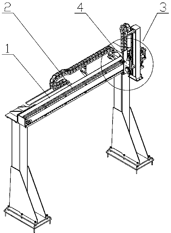
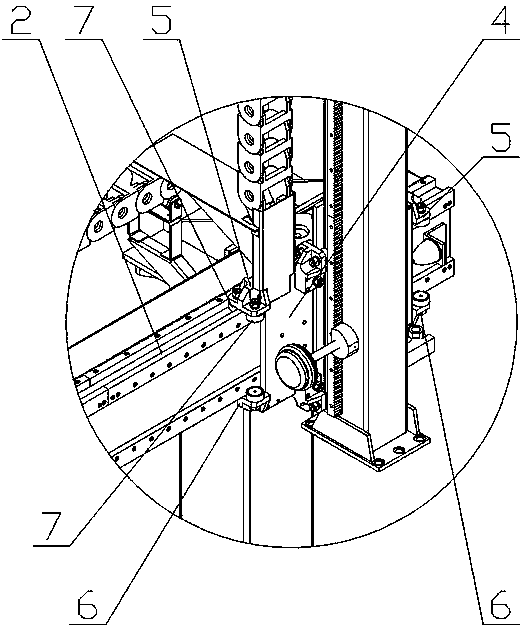
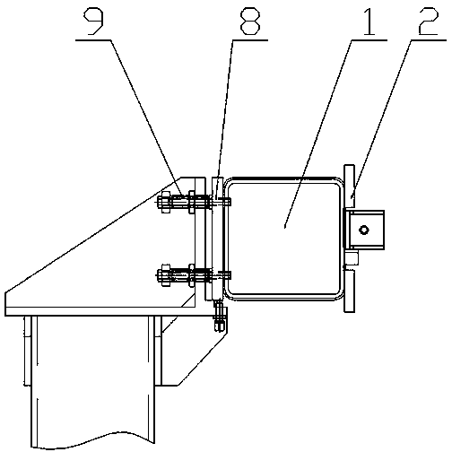
[0012] The specific implementation manner of the present invention will be described below with reference to the accompanying drawings. Such as figure 1 , figure 2 , image 3 Shown: a high-speed heavy-duty truss manipulator, including two symmetrically arranged legs, a beam 1 is supported between the two legs, a guide rail 2 is connected to the beam 1 through an adjustment mechanism, and a lifting device 3 is connected to the guide rail 2 Sliding connection, that is, the lifting device 3 can slide laterally on the guide rail 2, and two upper roller groups 5 and two lower roller groups 6 are symmetrically arranged on the base 4 of the lifting device 3, and each roller group is composed of two symmetrical roller groups. The set rollers 7 are formed, and these two rollers 7 are also located on both sides of the guide rail 2, that is to say, the two rollers 7 clamp the guide rail 2, the upper roller set 5 is in contact with the upper part of the guide rail 2, and the lower roll...


PUM


Abstract

The invention discloses a high-speed and heavy-duty truss mechanical arm. The high-speed and heavy-duty truss mechanical arm comprises two supporting legs which are arranged symmetrically, a transverse beam (1) is supported between the two supporting legs, a guide rail (2) is fixedly connected to the transverse beam (1), and a lifting device (3) is in sliding connection with the guide rail (2). The high-speed and heavy-duty truss mechanical arm is characterized in that two upper roller sets (5) and two lower roller sets (6) are symmetrically arranged on a base (4) of the lifting device (3), each roller set is composed of two rollers (7), every two rollers (7) are clamped on two sides of the guide rail (2), the upper roller sets (5) make contact with the upper portion of the guide rail (2), and the lower roller sets (6) make contact with the lower portion of the guide rail (2). The high-speed and heavy-duty truss mechanical arm is simple in structure, ingenious in design, and capable of achieving high-speed movement in the heave-duty condition. Besides, accurate positioning of the mechanical arm can be guaranteed.

Description

technical field [0001] The invention relates to a manipulator structure, in particular to a high-speed heavy-duty truss manipulator. Background technique [0002] With the continuous development of the automated production industry, more and more industrial production activities use manipulators to pick and place workpieces. The manipulator has the advantages of accurate movement, fast production tempo, labor saving, and cost control. The traditional truss manipulator includes a The beam is slidingly connected with a lifting device through a slide rail. The lifting device is equipped with a manipulator, which uses the combination of lateral movement and longitudinal movement to realize the grabbing, moving and placing actions of the manipulator. However, the defects of the traditional truss manipulator are : Between the lifting device and the slide rail, a plurality of balls arranged in the slide rail are used as the sliding parts. If the heavy load is moved, on the one hand...

Claims


Application Information

Patent Timeline
IPC IPC(8): B65G47/90
Inventor 丁厚永吕明波刘延芝于晓鹏孙子轩
Owner DALIAN HAOSEN EQUIP MFG
Why Eureka
Try Eureka