Decompression valve device of lubricating oil supplementing mechanism

A technology of lubricating oil and pressure relief valve, which is applied in the direction of mechanical equipment, machines/engines, liquid variable capacity machinery, etc. It can solve problems such as unfavorable compressor normal operation, increased internal pressure of oil cup, rupture and damage, etc., to eliminate Abnormal lubricating oil level, easy processing and manufacturing, and convenient operation

Inactive Publication Date: 2013-11-27
CHENGDU TIANYI NATURAL GAS COMPRESSOR MFG
View PDF6 Cites 2 Cited by
  • Summary
  • Abstract
  • Description
  • Claims
  • Application Information

AI Technical Summary

Problems solved by technology

[0004] Aiming at the above-mentioned problem that the air in the lubricating part of the existing natural gas compressor is heated and expanded or the lubricating oil itself is gasified, the internal pressure of the oil cup will increase, resulting in leakage or even rupture of the oil cup, which is not conducive to the normal operation of the compressor. The present invention provides Pressure relief valve device for lubricating oil replenishment mechanism

Method used


Image

  • Decompression valve device of lubricating oil supplementing mechanism

Examples


Embodiment 1

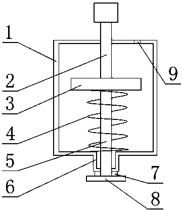
[0022] like figure 1 As shown, the pressure relief valve device of the lubricating oil replenishment mechanism includes a valve frame body 1, a pressure rod 2, a spring stopper 3, a spring 4, a pull rod 5, a rubber pad 7 and a rubber pad support block 8, and the spring stopper 3 The two ends are fixedly connected with one end of the pressure rod 2 and one end of the pull rod 5 respectively. Through holes are respectively arranged on the upper and lower ends of the valve frame 1. The pressure rod 2 forms a clearance fit with the through hole at the upper end. The pull rod 5 and the through hole at the lower end form a clearance fit, the other end of the pull rod 5 is fixedly connected to the rubber pad support block 8, and a rubber pad 7 is arranged between the rubber pad support block 8 and the valve frame body 1, and the spring 4 is arranged on the spring stopper 3 and the inner surface of the lower end of the valve frame body 1, the pressure rod 2 passes through the upper en...

Embodiment 2

[0025] This embodiment is further improved on the basis of embodiment 1, as figure 1 As shown, the pressure rod 2 and the pull rod 5 are integrated, and the pressure rod 2 and the pull rod 5 are all provided with external threads, the spring stopper 3 is provided with an internal thread through hole, and the spring stopper 3 and the The external threads are threadedly engaged.

[0026] This setting aims to realize the positional movement of the spring stopper 3 on the pull rod 5 and the push rod 2 by rotating the spring stopper 3 around the pressure rod 2 or the pull rod 5, that is, to achieve the purpose of adjusting the spring force of the spring 5 at any time.

[0027] It also includes an outer boss 6 , which is arranged at the bottom of the valve frame 1 , and the gap matching surface between the valve frame 1 and the pull rod 5 is at the bottom of the outer boss 6 .

[0028] The provided outer boss 6 is designed to accumulate lubricating oil entering the pressure relief...


PUM


Abstract

The invention discloses a decompression valve device of a lubricating oil supplementing mechanism. The device comprises a valve frame body, a press rod, a spring stop dog, a spring, a pull rod, a rubber gasket and a rubber gasket support block. Two ends of the spring stop dog are fixedly connected with one end of the press rod and one end of the pull rod, through holes are formed in the upper end face and the lower end face of the valve frame body, the press rod and the through hole in the upper end is in clearance fit, and the pull rod and the through hole in the lower end is in clearance fit. The other end of the pull rod is fixedly connected with the rubber gasket support block, the rubber gasket is arranged between the rubber gasket support block and the valve frame body, the spring is arranged between the spring stop dog and the lower end inner surface of the valve frame body, and the press rod penetrates the upper end face of the valve frame body and protrudes out of the valve frame body. The decompression valve device enables inner pressure of an oil cup to be released timely, prevents oil cup failure caused by the inner pressure and ensures the normal lubricating oil position of a lubricated part.

Description

technical field [0001] The invention relates to the field of lubricating oil compensating components of natural gas compressors, in particular to a pressure relief valve device of a lubricating oil replenishing mechanism. Background technique [0002] Natural gas compression generally adopts multi-stage compression, and piston compressors are mostly used in the prior art. During the working process of each stage of piston compressors, the crank main shaft bearing, crank pin and connecting rod big end bearing bush, crosshead pin and connecting rod Small head bushings, crossheads and slideways, compression cylinders, head packing seals, etc. all need lubricating oil for lubrication. It needs to be replenished in time. If the lubrication effect is not good, it will cause damage to the compressor and even cause more serious production accidents. [0003] In the prior art, in order to monitor the amount of lubricating oil in important lubricating parts, an oil cup is often set o...

Claims


Application Information

Patent Timeline
Patent Type & Authority Applications(China)
IPC IPC(8): F04B39/02
Inventor 孙伟余世春
Owner CHENGDU TIANYI NATURAL GAS COMPRESSOR MFG
Why Eureka
Try Eureka