
High return loss optical attenuation adjustable optical fiber connector and optical fiber connector group

An optical fiber connector, optical attenuation technology, applied in the direction of coupling of optical waveguides, can solve the problem of high return loss value cannot be guaranteed, and achieve the effect of high return loss value

Active Publication Date: 2016-02-03
GUANGXUN SCI & TECH WUHAN
View PDF7 Cites 0 Cited by
  • Summary
  • Abstract
  • Description
  • Claims
  • Application Information

AI Technical Summary

Problems solved by technology

[0005] In view of the above problems, the object of the present invention is to provide a high return loss optical fiber connector with adjustable optical attenuation and an optical fiber connector group, aiming to solve the problem that the existing optical fiber connector with adjustable optical attenuation cannot guarantee high attenuation value. Technical issues of return loss value

Method used


Image

  • High return loss optical attenuation adjustable optical fiber connector and optical fiber connector group
  • High return loss optical attenuation adjustable optical fiber connector and optical fiber connector group
  • High return loss optical attenuation adjustable optical fiber connector and optical fiber connector group

Examples


Embodiment Construction

[0024] In order to make the object, technical solution and advantages of the present invention clearer, the present invention will be further described in detail below in conjunction with the accompanying drawings and embodiments. It should be understood that the specific embodiments described here are only used to explain the present invention, not to limit the present invention.

[0025] In order to illustrate the technical solutions of the present invention, specific examples are used below to illustrate.

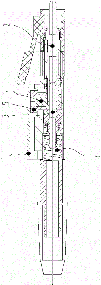
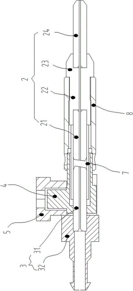
[0026] figure 1 It shows the axial cross-sectional structure of the optical fiber connector with adjustable high return loss optical attenuation provided by the embodiment of the present invention, figure 2 yes figure 1 In the structure of the optical fiber connector excluding the jacket 1 and the elastic component 6, only the parts related to the embodiment of the present invention are shown for convenience of description.

[0027] refer to figure 1 with figure 2...


PUM


Abstract

The invention belongs to the technical field of optical devices and provides a high-return-loss optical fiber connector with light decay adjustable and an optical fiber connector set. The high-return-loss optical fiber connector with the light decay adjustable comprises an outer sleeve, wherein a front insertion chip assembly and a rear insertion chip assembly are arranged in the outer sleeve, the front insertion chip assembly and the rear insertion chip assembly coincide in the axial direction and can not rotate relatively, a supporting block is further arranged in the outer sleeve, an adjusting disc which can rotate around the supporting block is further connected to the supporting block in a sleeved mode, an elastic assembly is further arranged at the tail end of the rear insertion chip assembly, part of the rear insertion chip assembly abuts against the edge of the adjusting disc all the time through the elastic assembly, and the distances between different positions of the edge of the adjusting disc and the axis are not totally equal to one another. According to the high-return-loss optical fiber connector with the light decay adjustable and the optical fiber connector set, the front insertion chip assembly and the rear insertion chip assembly can not rotate relatively, the adjusting disc can be rotated to push the rear insertion chip assembly to move in the axial direction, and then adjustment of a light decay value is achieved; due to the fact that the oblique end face of the front insertion chip assembly and the oblique end face of the rear insertion chip assembly are parallel to each other all the time, a high return loss value of the optical fiber connector can be kept all the time when the light decay value is adjusted.

Description

technical field [0001] The invention belongs to the field of optical devices, in particular to an optical fiber connector with adjustable high return loss optical attenuation and an optical fiber connector group. Background technique [0002] Optical fiber connectors are one of the necessary components for optical communication equipment, and are usually used to connect the optical path inlet and outlet ports of different devices and equipment. An optical attenuator is an optical device that can attenuate and adjust the power of an optical signal. [0003] The optical fiber connector with adjustable optical attenuation is a combination of optical connector and optical attenuator, which can meet the functional requirements of optical fiber connection and optical attenuation at the same time, and the optical attenuation value is adjustable. The current optical fiber connectors with adjustable optical attenuation have many shortcomings in terms of stability, functionality, and...

Claims


Application Information

Patent Timeline
Patent Type & Authority Patents(China)
IPC IPC(8): G02B6/38G02B6/26
Inventor 蒙冰张毓民赵小博杨宇翔
Owner GUANGXUN SCI & TECH WUHAN
Learn More