Reflector structure

A reflector and fixing mechanism technology, applied in the field of communication, can solve problems such as cost increase, and achieve the effects of improving return loss, reducing manufacturing cost and simple structure

Active Publication Date: 2013-08-28
HUAWEI TECH CO LTD
View PDF3 Cites 0 Cited by
  • Summary
  • Abstract
  • Description
  • Claims
  • Application Information

AI Technical Summary

Problems solved by technology

[0005] In order to solve the problem of cost increase caused by using FBG as a reflector in the prior art, the present invention proposes a reflector structure

Method used


Image

  • Reflector structure
  • Reflector structure
  • Reflector structure

Examples


Embodiment 1

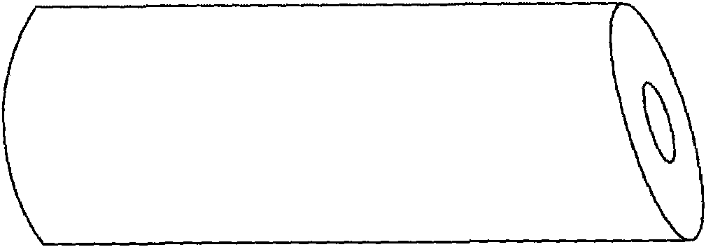
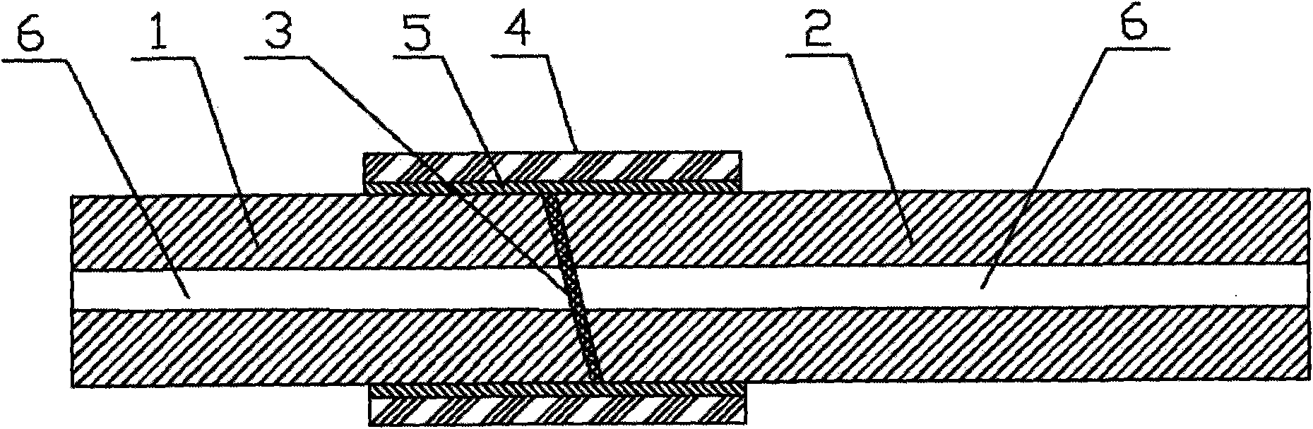
[0020] The first embodiment of the present invention proposes a reflector structure, including: a first ferrule 1 with an optical fiber 6 inside, a second ferrule 2 with an optical fiber 6 inside, the first ferrule 1 and the The second ferrule conducts 2; if figure 1 , figure 2 As shown, one end of the first ferrule 1 and the second ferrule 2 is a corresponding slope; and the slope of the first ferrule 1 and the second ferrule 2 is provided There is an inclined filter mechanism; and the first ferrule 1 and the second ferrule 2 are aligned and fixed by the fixing mechanism 4 .

[0021] Wherein, the filter mechanism is used to reflect light of some wavelengths and transmit light of some wavelengths.

[0022] In the embodiment of the present invention, an inclined filter film is arranged between the first ferrule and the second ferrule, so that the return loss of service light can be improved. The filter film can realize the reflection of some wavelengths of light and the tra...

Embodiment 2

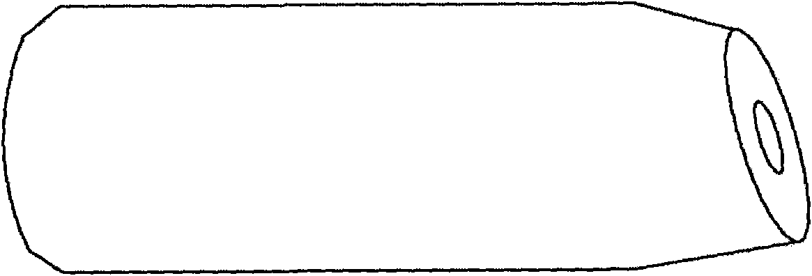
[0024] The first embodiment of the present invention proposes a reflector structure, including: a first ferrule 1 with an optical fiber 6 inside, a second ferrule 2 with an optical fiber 6 inside, the first ferrule 1 and the first ferrule 1 Two ferrule conduction 2; figure 1 , figure 2 As shown, one end of the first ferrule 1 and the second ferrule 2 is a corresponding slope; and the slope of the first ferrule 1 and the second ferrule 2 is provided There is an inclined filter mechanism 3 . Further, as image 3 As shown, a fixing mechanism 4 can also be provided to fix the first ferrule 1 and the second ferrule 2 so that the first ferrule 1 and the second ferrule 2 are aligned. Adhesives or matching fluids or air can also be provided to improve the reflective properties. Wherein, the adhesive can be: XOC, NORLAND81.

[0025] Among them, such as figure 1 , figure 2 As shown, the reflective structure is a filter film 3 . At the same time, if image 3 , Figure 4 As sh...

Embodiment 3

[0032] The third embodiment of the present invention proposes a method for manufacturing the reflector structure of the aforementioned first embodiment and the second embodiment, the process of which is as follows Figure 5 shown, including:

[0033] Step 101, forming a first inclined plane at one end of the first ferrule, forming a second inclined plane at the corresponding end of the second ferrule; and making the first inclined plane correspond to the inclination angle of the second inclined plane;

[0034] Step 102, forming a filter film on the first slope, the filter film closing the end of the first ferrule;

[0035] Step 103 , connecting the first slope of the first ferrule with the second slope of the second ferrule, so that the first ferrule and the second ferrule form a mutually conducting and sealed channel.

[0036] The method of the embodiment of the present invention can easily manufacture the reflector structures of the aforementioned first embodiment and the s...


PUM


Abstract

The invention provides a reflector structure belonging to the technical filed of communication. In the embodiment of the invention, the reflector structure comprises a first inserting core and a second inserting core, wherein the first inserting core and the second inserting core are communicated. The reflector structure is characterized in that one end part of the first inserting core and one end part of the second inserting core are corresponding slopes, and an inclined filtering mechanism is arranged between the slopes of the first inserting core and the second inserting core. According tothe embodiment of the invention, an inclined filter is arranged between the first inserting core and the second inserting core, thus improving service light return loss. The filter film can realize the reflection of light of certain wavelength and the transmission of light of certain wavelength, and precise connection between two inserting cores by a fixed mechanism. The reflector in the embodiment of the invention is simple in structure and convenient in assembly and the manufacturing cost and the total cost of the product can be lowered.

Description

technical field [0001] The invention relates to the communication field, in particular to a reflector structure. Background technique [0002] Optical communication technology is a commonly used technology, in which OLS (Optical Layer Supervisor, optical layer management) is mainly composed of OTDR (Optical Time Domain Reflectormeter, optical time domain reflector), optical switch, WDM, and reflector. OTDR couples the test light into the link through WDM, and reflects the test signal back through the reflector in the link, so as to judge whether there is a fault in the link. Therefore, a reflector needs to be connected to each link, and some important link monitoring points will also be connected to a reflector. [0003] In the process of realizing the present invention, the inventor finds that there are at least the following problems in the prior art: [0004] Most of the reflectors in the prior art use FBG (Fiber Bragg Grating, Fiber Bragg Grating), but the cost of FBG ...

Claims


Application Information

Patent Timeline
Patent Type & Authority Patents(China)
IPC IPC(8): G02B6/293
Inventor 单小磊禹金强张学明
Owner HUAWEI TECH CO LTD
Why Eureka
Try Eureka