
Low passive intermodulation coaxial connector test interface

a coaxial connector and low-passive intermodulation technology, applied in the direction of coupling device connection, electrical apparatus, two-part coupling device, etc., can solve the problems of incorrect test, damage to the connector, and time-consuming locking of the connector, so as to achieve low force, high return loss, and long life

Active Publication Date: 2018-03-20
SPINNER
View PDF15 Cites 0 Cited by
  • Summary
  • Abstract
  • Description
  • Claims
  • Application Information

AI Technical Summary

Benefits of technology

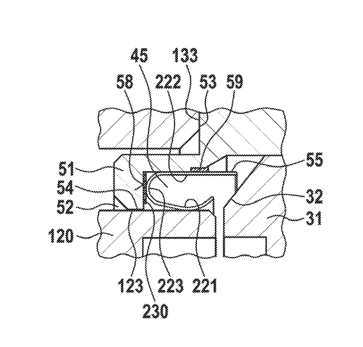
The invention is about a coaxial RF connector interface that has low passive intermodulation and high return loss. It can be easily connected and disconnected with low forces and maintained without losing performance even with many mating cycles. The connector has a spring holder with a contact spring that can be easily mounted without soldering or welding. The base of the connector is radially enclosing the contact fingers, resulting in a compact size and good impedance matching in a broad range of frequencies. The technical effect of this invention is to provide a reliable and high-performing coaxial RF connector interface for testing and measuring RF equipment.

Problems solved by technology

If an automatic connection between a device to be tested and a test adapter is desired, mechanical tolerances may cause severe problems.
This may lead to a misalignment of the connectors which may further lead to a damage of the connectors or to incorrect test results.
In a test setup, locking the connectors is too time consuming.
This is hardly feasible specifically in devices with a large number of connectors.
Furthermore, the connector should have a long lifetime with a large number of mating cycles as are required for test equipment.
This results in a very compact size of the overall assembly and short current paths between the outer conductors of the compatible coaxial connector and the test connector, which in turn leads to good impedance matching in a broad range of frequencies and, therefore, high return loss.

Method used


Image

  • Low passive intermodulation coaxial connector test interface
  • Low passive intermodulation coaxial connector test interface
  • Low passive intermodulation coaxial connector test interface

Examples


Embodiment Construction

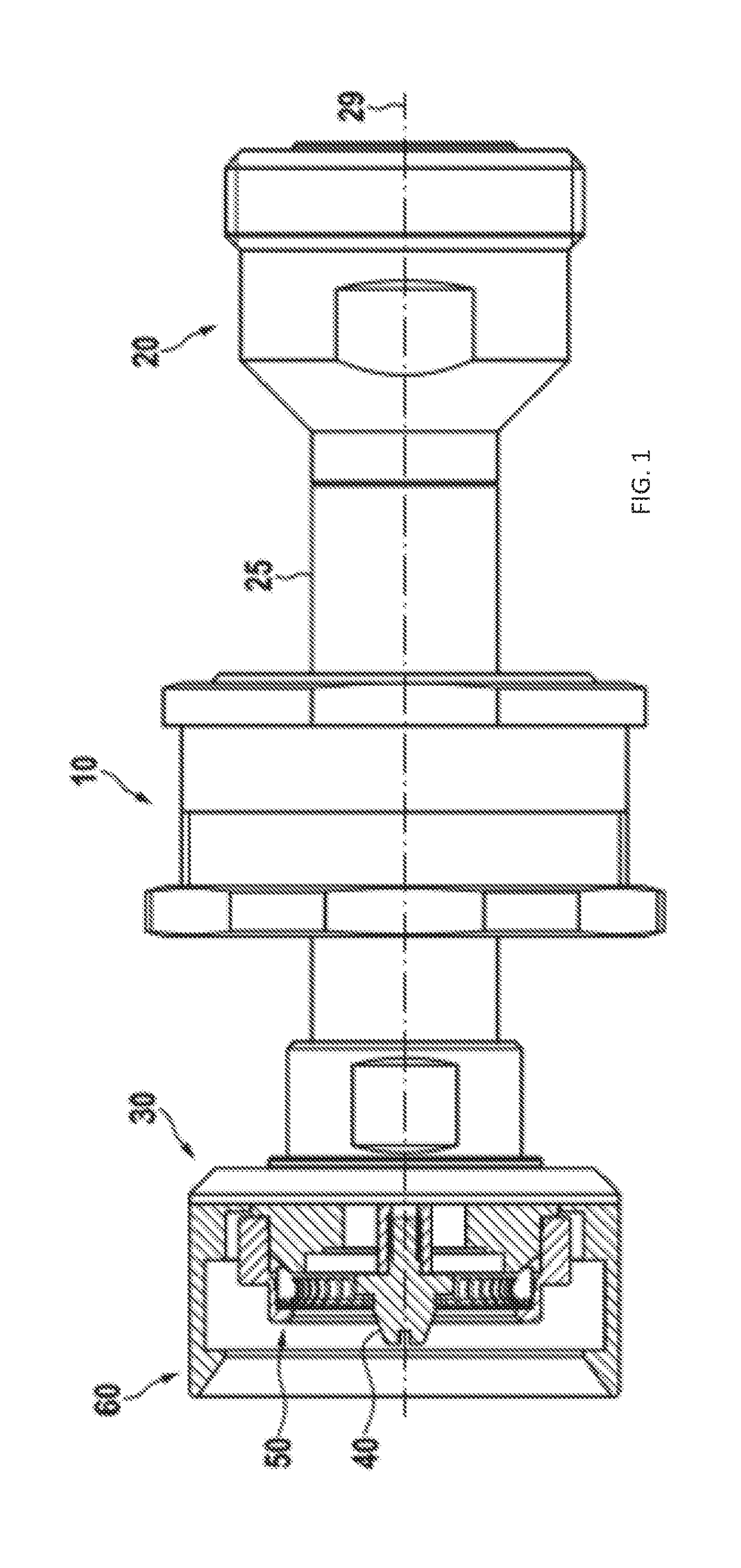
[0037]In FIG. 1, a preferred embodiment of a test connector assembly is shown. A test connector 30 is connected to an internal connector 20 by means of a connecting line component 25, which has a center axis 29, and which is held by a mounting suspension 10. The mounting suspension 10 is configured to optionally allow tilting of the connecting line component 25 and further allow a displacement thereof along the center axis 29. The test connector assembly is further structured to allow the application of force to the test connector 30 to simplify establishing a contact between a compatible coaxial connector 100, as will be shown in the next figure. Preferably, the test connector 30 comprises an inner conductor 40 and an outer conductor 50. It is further preferred, if the test connector 30 comprises a connector guide 60 configured to guide a compatible coaxial connector 100 when mating the connectors.

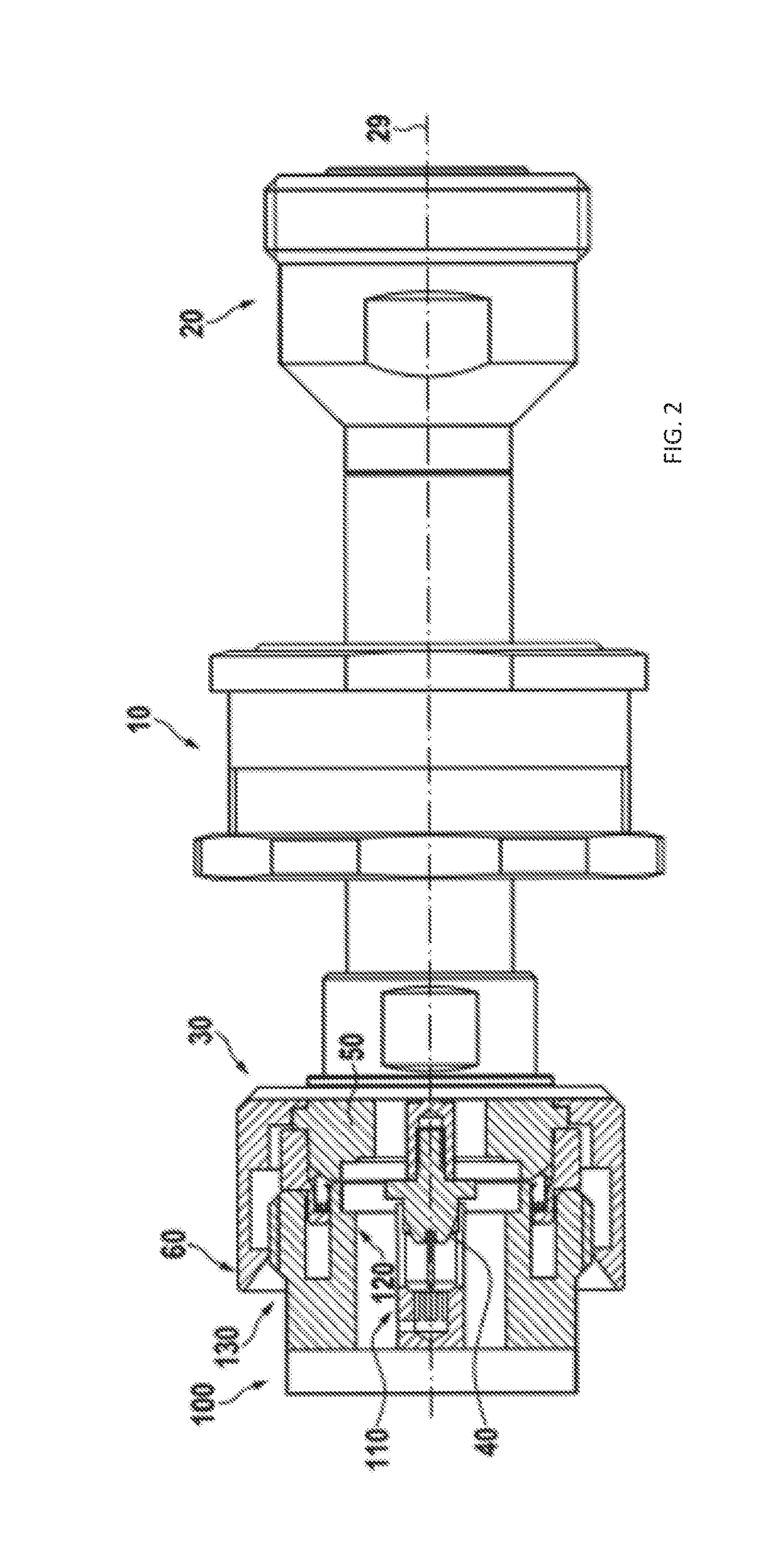
[0038]In FIG. 2, a preferred embodiment of a test connector assembly is shown with a ...


PUM


Abstract

A coaxial RF test connector comprises an inner conductor and an outer conductor arranged coaxially with respect to a center axis. The outer conductor includes a groove dimensioned to hold a circularly shaped contact spring. The contact spring includes a base portion and a plurality of arc-shaped contact fingers extending from the base with gaps between the individual contact fingers. The base has a radius larger than that at which the contact fingers are bent. The contact fingers have first contact section for contacting the outer conductor of a compatible coaxial connector in a direction radial to the center axis, and a second contact section for capacitively coupling to a sidewall of the groove.

Description

CROSS-REFERENCE TO RELATED APPLICATIONS[0001]This application is a continuation of the pending International Application No. PCT / EP2016 / 050451 filed on Jan. 12, 2016 and now published as WO 2016 / 116326, which designates the United States and claims priority from the European Application No. 15152199.4, which was filed on Jan. 22, 2015 and the European Application No. 15195915.2, which was filed on Nov. 23, 2015. The disclosure of each of the above-mentioned applications is incorporated by reference herein.BACKGROUND1. Field of the Invention[0002]The invention relates to a coaxial test connector configured for easy and quick connection to a test object. It further relates to a self-aligning coaxial connector, i.e. a connector, which automatically aligns to a mating connector during the coupling operation.2. Description of Relevant Art[0003]For testing electronic devices test adapters are often used. These test adapters connect with devices to be tested to external test equipment. Whe...

Claims


Application Information

Patent Timeline
Patent Type & Authority Patents(United States)
IPC IPC(8): H01R24/40H01R103/00
CPCH01R24/40H01R2103/00H01R13/193H01R13/521H01R13/622H01R13/6583
Inventor GRASSL, MARTINZISSLER, WOLFGANGGRABICHLER, ANDREAS
Owner SPINNER
Learn More