

Exposure apparatus and exposure method
An exposure device and technology to be exposed, applied in the field of substrate manufacturing, can solve the problems of surface morphology developer damage, reduced product performance indicators, loose pattern structure, etc. The effect of structural stabilization
- Summary
- Abstract
- Description
- Claims
- Application Information
AI Technical Summary
Problems solved by technology
Method used
Image

Examples
Embodiment Construction
[0030] The technical solutions in the embodiments of the present invention will be clearly and completely described below in conjunction with the accompanying drawings in the embodiments of the present invention. Obviously, the described embodiments are only some, not all, embodiments of the present invention.
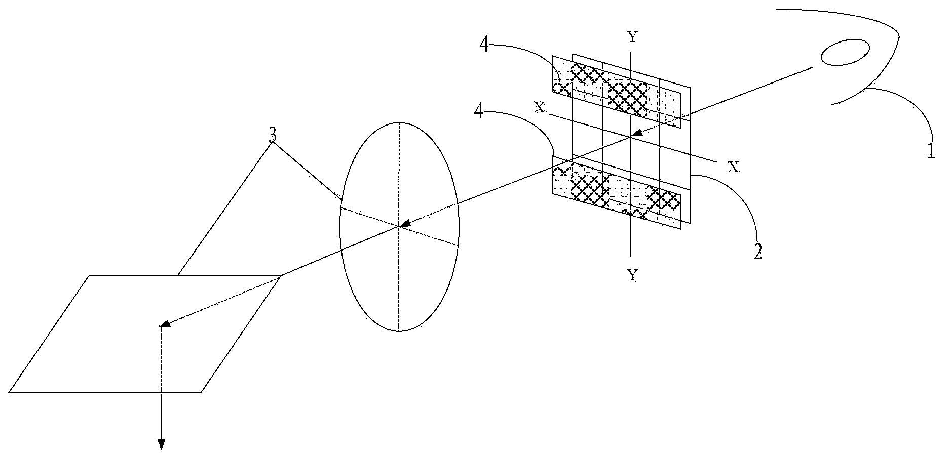
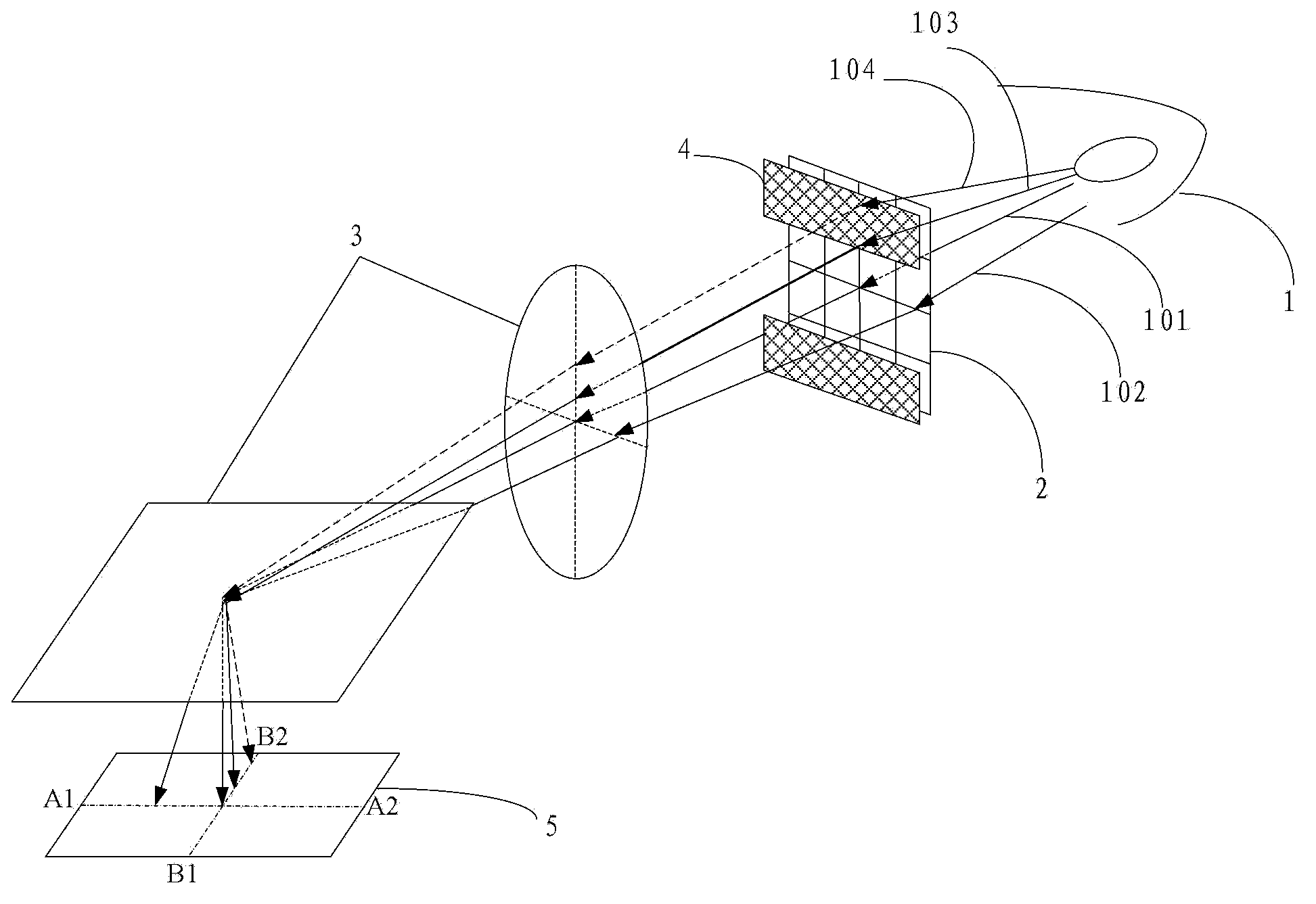
[0031] An embodiment of the present invention provides an exposure device, such as figure 1 As shown, the exposure device includes: an exposure light source 1, a compound eye system 2, an optical system 3, and two diaphragms 4, and the two diaphragms 4 are arranged on the incident surface side or the exit surface of the compound eye system 2 One side, and the two diaphragms 4 are arranged symmetrically with respect to the center of the compound eye system 2; wherein, the orientation of the opening formed by the two diaphragms 4 (hereinafter referred to as the opening orientation) depends on the key of the component to be exposed Size orientation adjustment.
[0032] H...
PUM
 Abstract
Description
Claims
Application Information