
Method for manufacturing light-variable light-emitting component

A manufacturing method and technology of light-emitting components, applied in the direction of electrical components, electric solid-state devices, semiconductor devices, etc., can solve problems such as cost-consuming, not in line with economic benefits, and affect the applicability of light-emitting component modules, so as to reduce the probability of inoperability, The effect of increasing the diversity of luminous colors

Inactive Publication Date: 2013-11-27
EVERLIGHT ELECTRONICS
View PDF3 Cites 0 Cited by
  • Summary
  • Abstract
  • Description
  • Claims
  • Application Information

AI Technical Summary

Problems solved by technology

[0004] However, with such a circuit structure design, when part of the light-emitting diode chips are burned, the entire light-emitting component module cannot operate normally, which seriously affects the applicability of the light-emitting component module.
Moreover, when part of the light emitting diode chips of the light emitting component module are burnt out, the light emitting component module can only be disassembled again, and the damaged light emitting diode chip in the light emitting component module can be replaced to make the light emitting component module operate smoothly and normally. It is labor-intensive and cost-intensive
Therefore, the circuit structure design of the traditional light-emitting component module is not economical
[0005] In addition, in the current phosphor powder coating technology, phosphor powder can only be coated on multiple or all LED chips in the same light-emitting component package at the same time, but cannot be used for each light-emitting diode chip located in the same light-emitting component package. Diode chips coated with different phosphors
[0006] Therefore, due to the limitation of phosphor powder coating technology, the application range of light-emitting component modules is limited

Method used


Image

  • Method for manufacturing light-variable light-emitting component
  • Method for manufacturing light-variable light-emitting component
  • Method for manufacturing light-variable light-emitting component

Examples


Embodiment Construction

[0039] The invention discloses a dimming light-emitting component, which has wide applicability. In order to make the narration of the present invention more detailed and complete, refer to the following description and cooperate Figure 1 to Figure 4 attached drawings.

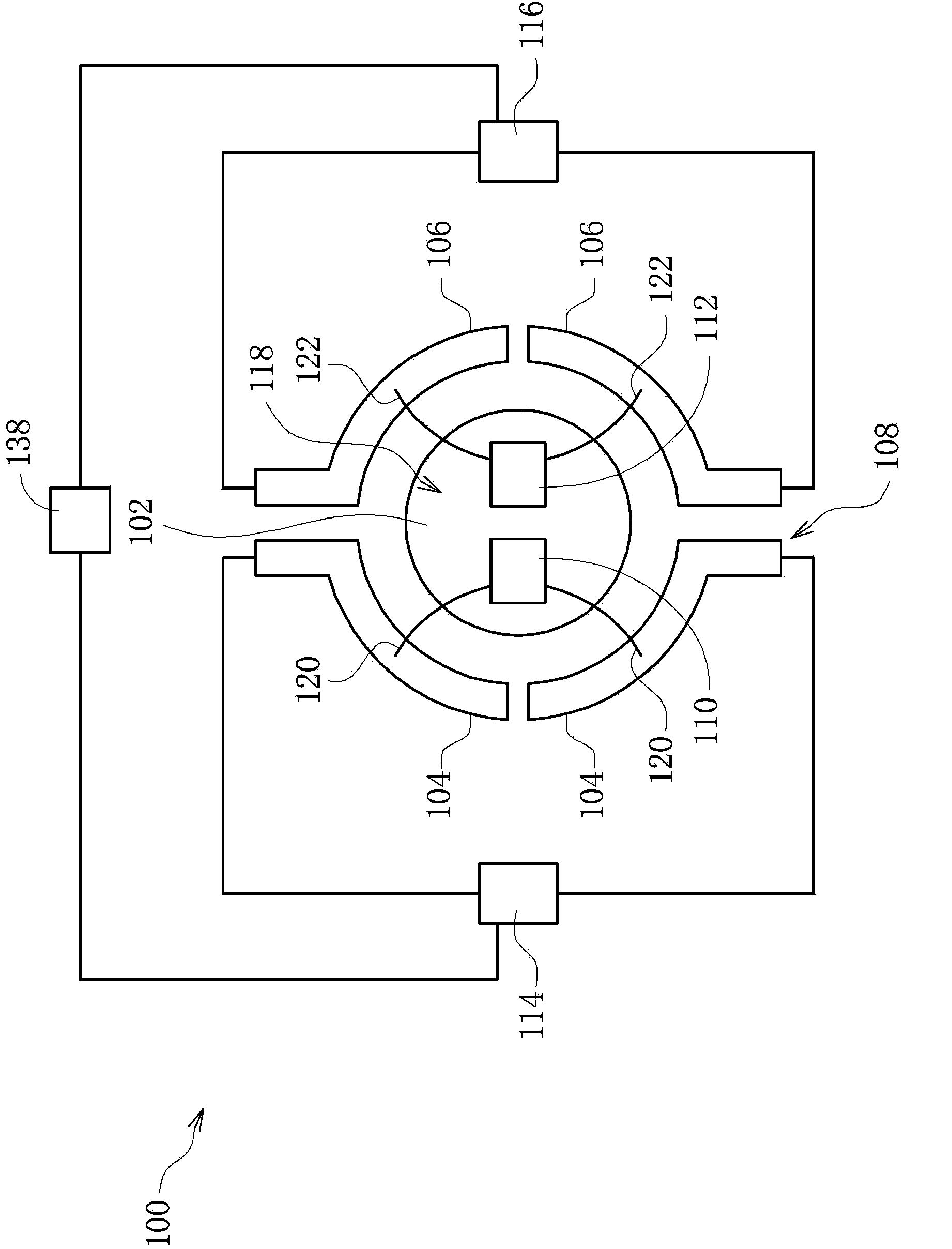
[0040] Please refer to figure 1 , which is a schematic top view showing a dimming light-emitting component according to an embodiment of the present invention. In one embodiment, the dimming light-emitting component 100 mainly includes a bracket 108 , at least two light-emitting chips 110 and 112 , and at least two independent power sources 114 and 116 . The independent power sources 114 and 116 are respectively electrically connected to the corresponding light-emitting chips 110 and 112 to supply the required power.

[0041] In one embodiment, the bracket 108 may include a chip carrier 102 and at least two pairs of pins 104 and 106 .

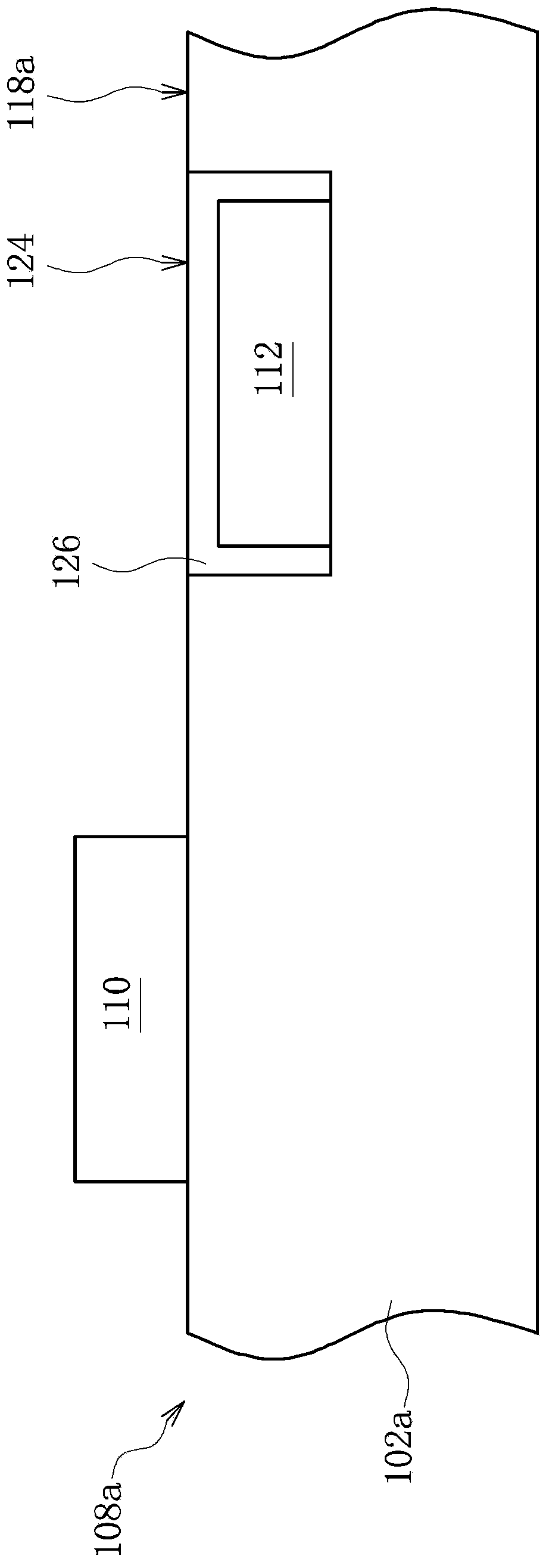
[0042] Please refer to figure 2 , which is a cross-sectional view o...


PUM


Abstract

The invention relates to a method for manufacturing a light-variable light-emitting component. The method comprises the steps of providing a light-emitting chip configured on a bearing base; providing a first shield with a first opening enabling the light-emitting chip to be exposed; providing a spraying device configured above the first shield to carry out a first spraying manufacturing procedure, wherein the spraying device sprays first fluorophor solutions back and forth along a first path, and one light emitting face and multiple side surfaces of the light-emitting chip are coated by the first fluorophor solutions conformally; carrying out a solidification manufacturing procedure to enable the first fluorophor solutions coating the surface of the light-emitting chip to be solidified to be a first conformal fluorescence coating layer.

Description

[0001] This application is a divisional application of a Chinese invention patent application with an application date of November 9, 2009, an application number of 200910211888.2, and an invention title of "Dimmable Light-emitting Component and Its Manufacturing Method". technical field [0002] The present invention relates to a manufacturing method of a light-emitting component, and in particular to a manufacturing method of a light-changing light-emitting component. Background technique [0003] When conventional light emitting diode chips (LED chips) are applied to light emitting component modules, a series-parallel structure circuit is used to connect these light emitting diode chips. [0004] However, with such a circuit structure design, when part of the LED chips are burned, the entire light-emitting component module cannot operate normally, which seriously affects the applicability of the light-emitting component module. Moreover, when part of the light emitting di...

Claims


Application Information

Patent Timeline
Patent Type & Authority Applications(China)
IPC IPC(8): H01L25/075H01L33/50
CPCH01L2224/48091
Inventor 陈群鹏赵自皓郭信男
Owner EVERLIGHT ELECTRONICS
Features
  • Generate Ideas
  • Intellectual Property
  • Life Sciences
  • Materials
  • Tech Scout
  • Unparalleled Data Quality
  • Higher Quality Content
  • 60% Fewer Hallucinations
Learn More