A reactive power compensation equipment configuration method for a large-scale wind power external transmission system

A technology of compensation equipment and configuration method, which is applied in reactive power compensation, reactive power adjustment/elimination/compensation, flexible AC transmission system, etc., and can solve problems such as partial optimism

Active Publication Date: 2015-09-23
PLANNING EVALUATION CENT SHAANXI ELECTRIC POWER +2
View PDF2 Cites 2 Cited by
  • Summary
  • Abstract
  • Description
  • Claims
  • Application Information

AI Technical Summary

Problems solved by technology

This method often leads to double counting of the low-capacity compensation capacity in the substation, so it is easy to draw an optimistic conclusion; and this method is powerless when dealing with network structures

Method used


Image

  • A reactive power compensation equipment configuration method for a large-scale wind power external transmission system
  • A reactive power compensation equipment configuration method for a large-scale wind power external transmission system
  • A reactive power compensation equipment configuration method for a large-scale wind power external transmission system

Examples


Embodiment 1

[0108] Figure 4 It is a schematic diagram of the 750kV second channel of Xinjiang and the Northwest main network, and the configuration scheme of the line high voltage reactor is marked in the figure. The full line high resistance compensation of the second channel is 84%.

[0109] Firstly, the capacitive reactive power demand of each substation in the network channel is analyzed, and the reactive power hierarchical partition method proposed in the invention is adopted, and the heavy load mode of the power flow in 2015 is considered, and the reactive power demand under the N-1 mode of line heavy load is considered. Table 4, Table 5, and Table 6 show the reactive power loss of transformers in each substation of the second channel of the network under the heavy load mode in 2015, the reactive power loss of each line, and the capacitive reactive power demand of each substation. Further, considering the reactive power demand of each line N-1 of the second channel under the heavy...

Embodiment 2

[0138] Analyze the inductive reactive power demand of each substation in the network channel. According to the demand analysis method proposed by the invention, that is, 100% compensation for the charging power of the newly added lines of the project. Considering the no-load mode in 2015, the inductive reactive power deficit of each line of the second network channel is shown in Table 9 below, and the inductive reactive power demand of each station is shown in Table 10 below.

[0139] Table 9 Inductive reactive power deficit of each line of the second channel

[0140]

[0141] Table 10 Inductive reactive power demand of each station in the second channel

[0142]

[0143] According to Table 10, there are inductive reactive power demands in Hami Station, Hami South Station, Dunhuang Station, Shazhou Station, and Qaidam Station in the second channel of Xinjiang and Northwest Main Network, and there are inductive reactive power demands in Hami Converter Station and Yuka St...

Embodiment 3

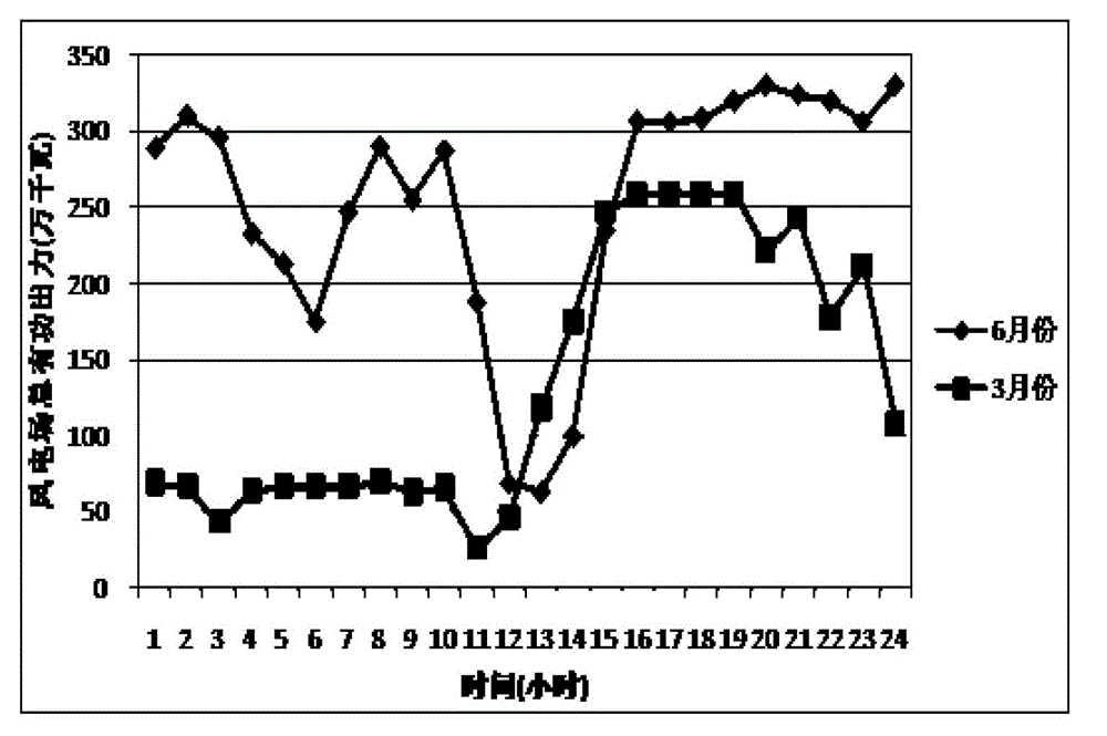
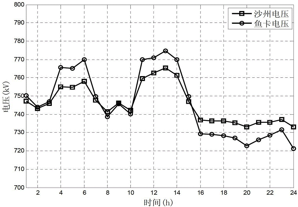
[0159] Analyze the voltage regulation effect of reactive power compensation configuration. Under the heavy load mode in 2015, considering wind power fluctuations, the typical output of wind farms in June was used as an example to carry out simulation calculations, as shown in figure 2 shown. The initial input of the four groups of 390Mvar controllable high resistance of the Shazhou-Yuka two-circuit line is its maximum capacity, that is, 390Mvar. When the wind power output changes, the four groups of controllable high-resistance lines of the Shazhou-Yuka line are switched simultaneously according to the voltage regulation, so as to ensure that the operating voltage of the 750kV side of each station in the system is within the range of 750kV~790kV. Once the voltage is lower than 750kV, the four groups of controllable high resistance are cut off; once the voltage is higher than 790kV, the four groups of controllable high resistance are switched on. At the same time, during the...


PUM


Abstract

The present invention belongs to the field of electric power systems, and in particular, relates to an application solution for a reactive compensation device of a large-scale wind power transmission system. Aiming at a large-scale wind power transmission system, taking the satisfaction of the demand for power transmission and wind power integration as an objective, and by means of the reactive balance analysis under different operation modes in different level years, proposed are capacitive and inductive reactive demands of each transformer station in the system, and also proposed is a configuration solution of a low-voltage side fixed switching reactive compensation device such as a capacitor, a reactor and the like, and a dynamic reactive compensation device such as a controllable reactor, a static reactive compensator and the like. The proposed configuration solution can ensure that the voltage at each point of the system is controlled within a reasonable range under different operation modes, while a dynamic reactive compensation device can satisfy the reactive control requirements for the grid voltage during wind power fluctuations, and has a very strong engineering adaptability.

Description

technical field [0001] The invention relates to the field of power systems, in particular to a method for configuring reactive power compensation equipment of a large-scale wind power external transmission system. Background technique [0002] At present, the problem of dynamic reactive power compensation caused by wind power active power fluctuations is particularly prominent. Proposing a reasonable and feasible reactive power compensation configuration scheme for each substation in the second channel project is very critical to ensure that the voltage at each point in the system is controlled within a reasonable range under different operating modes and wind power fluctuations. [0003] In the 750kV system, it is the first time in China to adopt the method of layering and partitioning for reactive power balance analysis. The currently commonly used reactive power balance analysis method is generally only for chain power transmission projects, with the section-by-section l...

Claims


Application Information

Patent Timeline
Patent Type & Authority Patents(China)
IPC IPC(8): H02J3/18
CPCY02E10/763H02J3/1871H02J3/1864Y02E40/30H02J3/386H02J3/1835H02J3/1821H02J2300/28H02J3/381Y02E10/76Y02E40/10Y04S20/222Y02B70/3225H02J3/50
Inventor 喻新强王雅婷王劲武申洪孙强周勤勇王中阳秦晓辉郑楠
Owner PLANNING EVALUATION CENT SHAANXI ELECTRIC POWER
Why Eureka
Try Eureka