Novel motor rotor automobile circlip pressing machine

A motor rotor and circlip technology, which is applied in the field of mechanical processing, can solve the problems of complex structure of the circlip machine for the motor rotor, poor intuition of the processing process, and high failure maintenance rate, and achieves the effects of simple structure, low cost and low failure rate.

Inactive Publication Date: 2013-11-27
HUZHOU YONGCHANG BEISHITUO ELECTRIC APPLIANCE INDAL
View PDF1 Cites 17 Cited by
  • Summary
  • Abstract
  • Description
  • Claims
  • Application Information

AI Technical Summary

Problems solved by technology

[0002] The existing motor rotor circlip press machine has complex structure and low working efficiency. For example, the patent publication No. CN102001081A with the publication date of 2011-04-06 discloses an automatic circlip installation device, including a positioning device, located in the positioning The feeding device above the device, the storage device fixed on the feeding device; a chute is arranged between the feeding device and the barrel, and the feeding device is located at the front end of the chute There is a feeding through hole; the rear end of the feeding device is provided with a first driving device along the horizontal direction, and the free end of the first driving device is connected with a push plate that can slide inside the chute; the feeding device A second driving device is arranged along the height direction on the upper side, and the free end of the driving device is connected with a top that can be inserted into the feeding through hole.
The structure of this device is complicated, the processing process is not intuitive, the efficiency of rotor transmission and installation is low, and the failure maintenance rate is high.

Method used


Image

  • Novel motor rotor automobile circlip pressing machine
  • Novel motor rotor automobile circlip pressing machine
  • Novel motor rotor automobile circlip pressing machine

Examples


Embodiment Construction

[0032] The present invention will be described in further detail below in conjunction with the accompanying drawings.

[0033] This specific embodiment is only an explanation of the present invention, and it is not a limitation of the present invention. Those skilled in the art can make modifications to this embodiment without creative contribution as required after reading this specification, but as long as they are within the rights of the present invention All claims are protected by patent law.

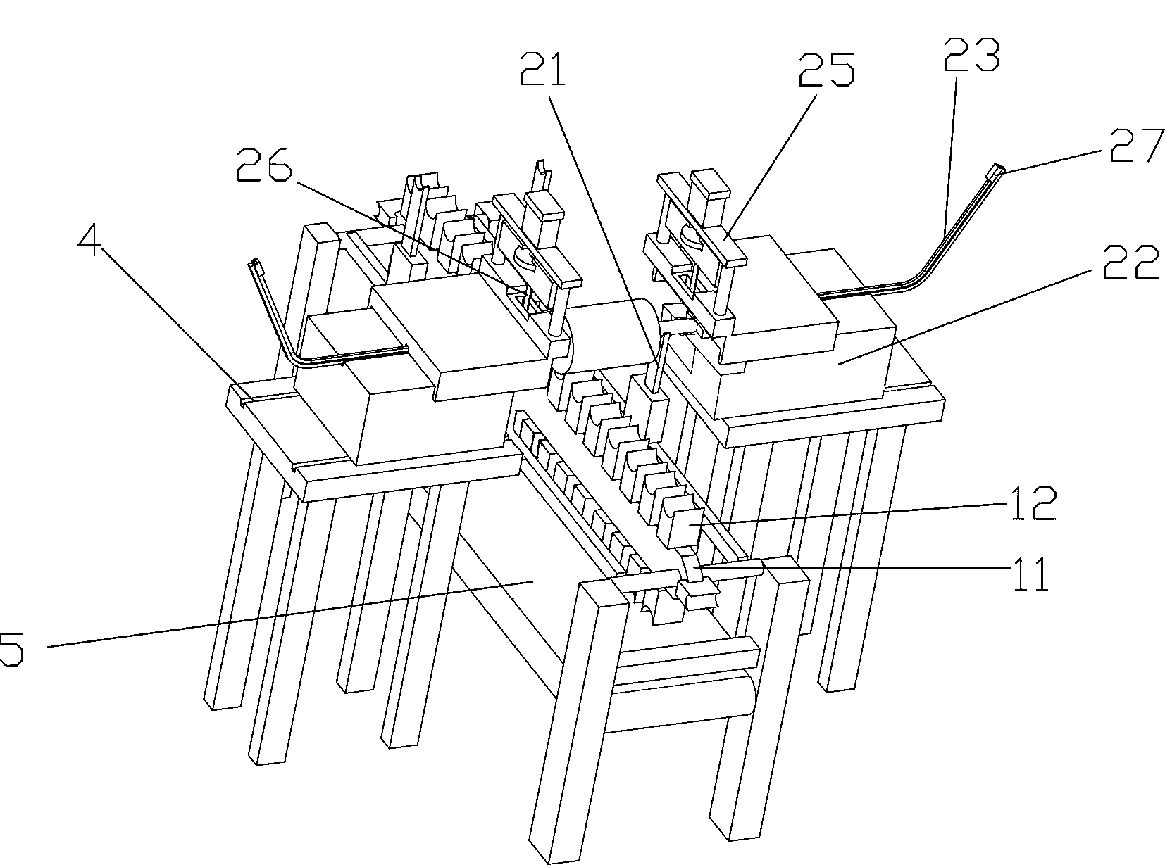
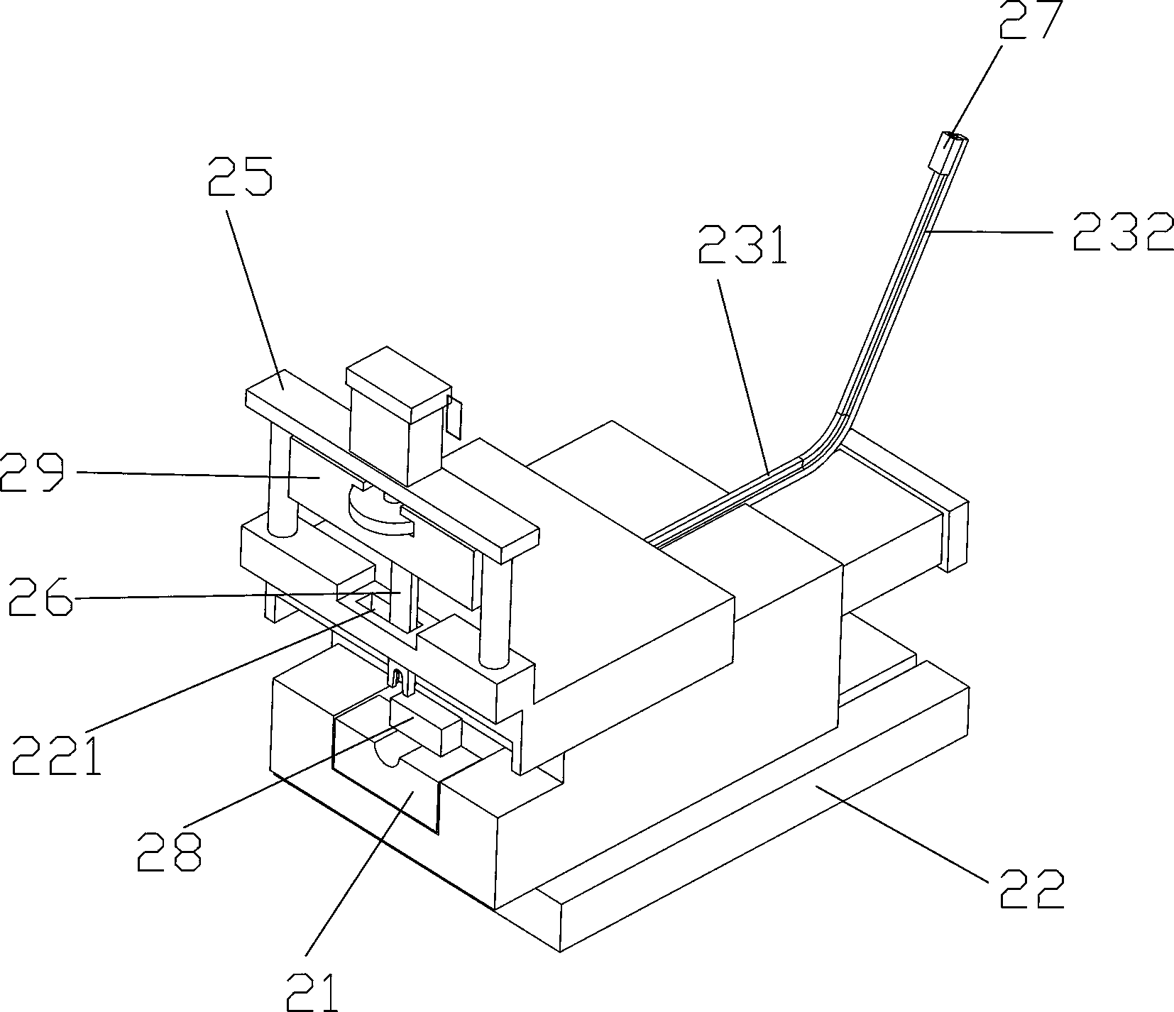
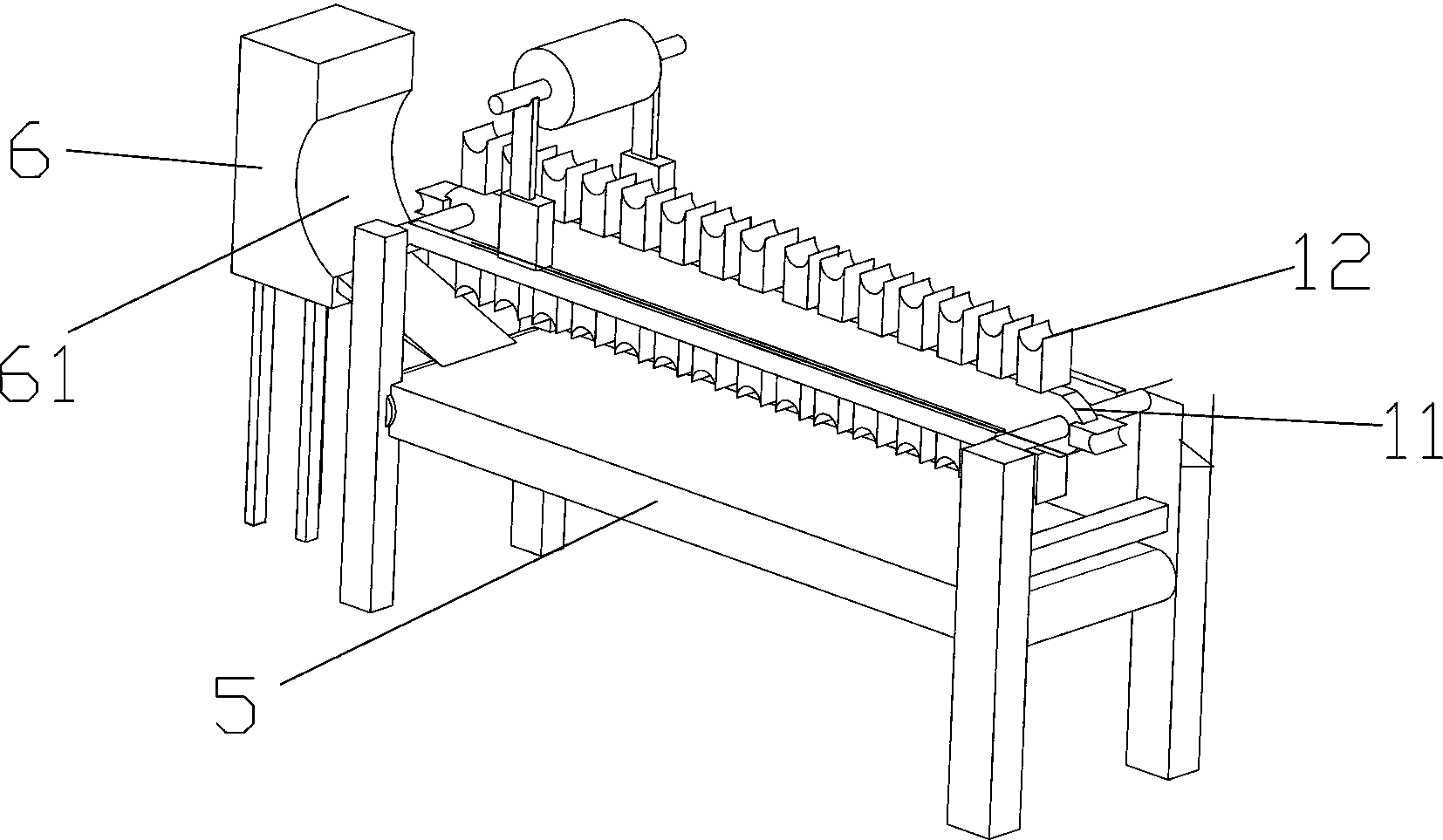
[0034] A new type of motor rotor automatic clamp ring pressing machine, including a frame, on which a transmission device and a clamp spring device for conveying the rotor are arranged. The transmission device includes a chain 11 and a chain 11 for carrying the rotor. The rotor holder 12 with a bracket on the top; the clamping spring device includes a pair of clamping spring mechanisms respectively arranged on both sides of the chain 11 to press the two clamping springs to both en...


PUM


Abstract

The invention relates to the technical field of machining, in particular to a novel motor rotor automatic circlip pressing machine. The machine comprises a machine frame. The machine frame is provided with a conveying device used for conveying rotors and a circlip pressing device. The conveying device comprises a chain and rotor supports, wherein the rotor supports are arranged on the chain and used for carrying the rotors, and the top of each rotor support is provided with a supporting groove; the circlip pressing device comprises a pair of circlip pressing mechanisms, wherein the circlip pressing mechanisms are arranged on the two sides of the chain respectively and enable two circlips to be pressed at the two ends of a rotor shaft respectively at the same time. Each circlip pressing mechanism comprises a jacking supporting block used for supporting the rotors and a horizontal positioning block, wherein the horizontal positioning block abuts against the rotors at the end of the rotor shaft, can position the rotors jacked by the jacking supporting block and can move in the horizontal direction. The novel motor rotor automatic circlip pressing machine is fast to install, high in rotor conveying and circlip pressing efficiency, high in automation degree, little in manpower investment and high in work efficiency.

Description

technical field [0001] The invention relates to the technical field of mechanical processing, in particular to a novel motor rotor automatic spring pressing machine. Background technique [0002] The existing motor rotor circlip press machine has complex structure and low working efficiency. For example, the patent publication No. CN102001081A with the publication date of 2011-04-06 discloses an automatic circlip installation device, including a positioning device, located in the positioning The feeding device above the device, the storage device fixed on the feeding device; a chute is arranged between the feeding device and the barrel, and the feeding device is located at the front end of the chute There is a feeding through hole; the rear end of the feeding device is provided with a first driving device along the horizontal direction, and the free end of the first driving device is connected with a push plate that can slide inside the chute; the feeding device A secon...

Claims


Application Information

Patent Timeline
Patent Type & Authority Applications(China)
IPC IPC(8): H02K15/02
Inventor 汪旭亮孙永庆孙豪远
Owner HUZHOU YONGCHANG BEISHITUO ELECTRIC APPLIANCE INDAL
Why Eureka
Try Eureka