Parameter design method of grid-connected inverter LLCL filter

A parameter design and filter technology, applied in the direction of output power conversion devices, electrical components, etc., can solve the problem of lack of effective parameter design methods for LLCL filters, and achieve the effect of reducing the difficulty of design

Active Publication Date: 2013-11-27
HEFEI UNIV OF TECH
View PDF5 Cites 20 Cited by
  • Summary
  • Abstract
  • Description
  • Claims
  • Application Information

AI Technical Summary

Problems solved by technology

[0004] Purpose of the present invention is exactly to solve the

Method used


Image

  • Parameter design method of grid-connected inverter LLCL filter
  • Parameter design method of grid-connected inverter LLCL filter
  • Parameter design method of grid-connected inverter LLCL filter

Examples


Embodiment Construction

[0027] This embodiment takes a 5KW grid-connected inverter system as an example to illustrate a parameter design method for the LLCL filter of the grid-connected inverter. DC side voltage U dc =200(V), grid-connected inverter switching frequency ω sw =20000π(rad / s), fundamental frequency ω 0 =100π(rad / s).

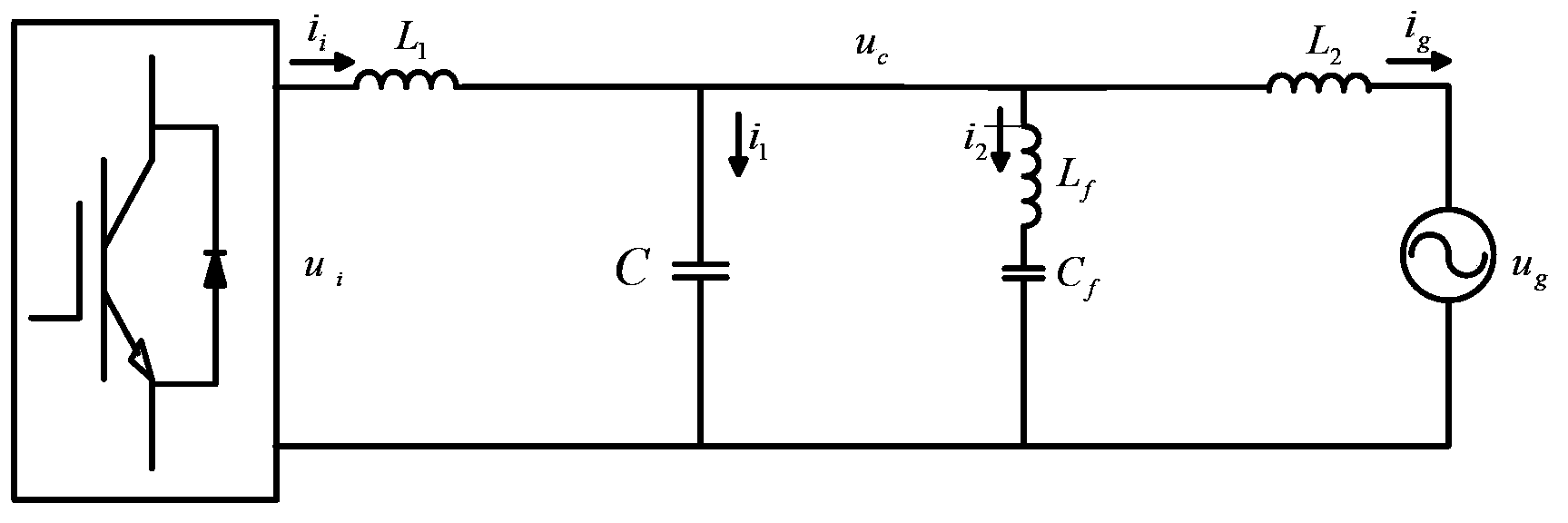
[0028] figure 1 Shown is the schematic diagram of the LLCL filter circuit, which outputs the voltage u from the inverter i to grid side current i g The transfer function of is:

[0029] G LLCL ( s ) = L f C f s 2 + 1 L 1 L 2 L f ...


PUM


Abstract

The invention provides a parameter design method of a grid-connected inverter LLCL filter. The method mainly aims to decompose complex LLCL filter parameter design into corresponding traditional LCL filter parameter design and parameter design of a series resonance branch circuit. The method comprises the following steps that firstly, parameters of the LLCL filter according to the parameter design method of a traditional LCL filter are initialized, wherein the parameters include bridge arm side inductance L1, power grid side inductance L2 and total capacitance Ct; secondly, parallel-connection filtering capacitance C of the LLCL filter, resonance capacitance Cf of the LC resonance branch circuit and resonance capacitance Lf of the LC resonance branch circuit are calculated according to the parameters of the LLCL filter obtained in the step one; thirdly, parameter values selected in the step one and the step two are verified. If the verification passes, the parameter design is completed; if the verification does not pass, a user returns to the step one, and new round of parameter selection is performed.

Description

technical field [0001] The invention relates to a parameter design method of a grid-connected inverter filter, in particular to a parameter design method of a grid-connected inverter LLCL filter. Background technique [0002] In the grid-connected inverter, in order to reduce the harmonic component of the output current, the inverter needs to be connected to the grid through a filter to filter out the switching harmonics generated by the inverter. The Chinese invention patent with the application number 201210293896.8 proposes an LLCL filter, which is composed of a main filter, an auxiliary filter, a bypass capacitor, and a resonant branch composed of an inductor and a capacitor, which is about the traditional LCL filter The capacitive branch of the filter is changed to a resonant circuit of a specific frequency (usually the switching frequency) to provide a bypass channel for the main harmonic current, thereby reducing the total inductance of the filter. [0003] But so fa...

Claims


Application Information

Patent Timeline
IPC IPC(8): H02M1/12
Inventor 张兴李飞朱虹施洋洋余畅舟刘芳刘淳
Owner HEFEI UNIV OF TECH
Why Eureka
Try Eureka