Synchronously-ejecting welding mechanism for lower welding of steel bar trusses

A technology of steel bar truss and welding mechanism, applied in the field of steel bar truss, can solve the problems of the lower welding mechanism being unable to lift, unable to lift at the same time, unable to handle welding requirements of different specifications, etc., to achieve the effect of simple structure

Inactive Publication Date: 2013-12-04
WUXI WEIHUA ELECTRIC WELDING MFG
7 Cites 1 Cited by

AI-Extracted Technical Summary

Problems solved by technology

The lower welding process is realized through the welding of the lower welding mechanism. In the prior art, the lower welding mechanism cannot be raised o...

Abstract

The invention relates to a synchronously-ejecting welding mechanism for the lower welding of the steel bar trusses, which is particularly used for synchronously welding the steel bar trusses and belongs to the technical field of the steel bar trusses. The synchronously-ejecting welding mechanism for the lower welding of the steel bar trusses comprises a synchronous connecting rod, wherein two ends of the synchronous connecting rod are connected with a first synchronous gear and a second synchronous gear respectively; a first speed reducer and a third speed reducer are symmetrically arranged on a first frame; the first speed reducer and the third speed reducer are connected by a first transmission connecting rod; two ends of the first transmission connecting rod are connected with the first frame through a first transmission connecting rod seat; the middle part of the first transmission connecting rod is provided with a first bevel gear; the first bevel gear is connected with the first synchronous gear in an engagement way. The welding mechanism provided by the invention is adjustable so as to be capable of meeting various specifications, as well as be available for simultaneous adjustment and synchronous lifting.

Application Domain

Resistance electrode holders

Technology Topic

RebarWelding +1

Image

  • Synchronously-ejecting welding mechanism for lower welding of steel bar trusses
  • Synchronously-ejecting welding mechanism for lower welding of steel bar trusses
  • Synchronously-ejecting welding mechanism for lower welding of steel bar trusses

Examples

  • Experimental program(1)

Example Embodiment

[0012] The present invention will be further described below in conjunction with the embodiments in the accompanying drawings:
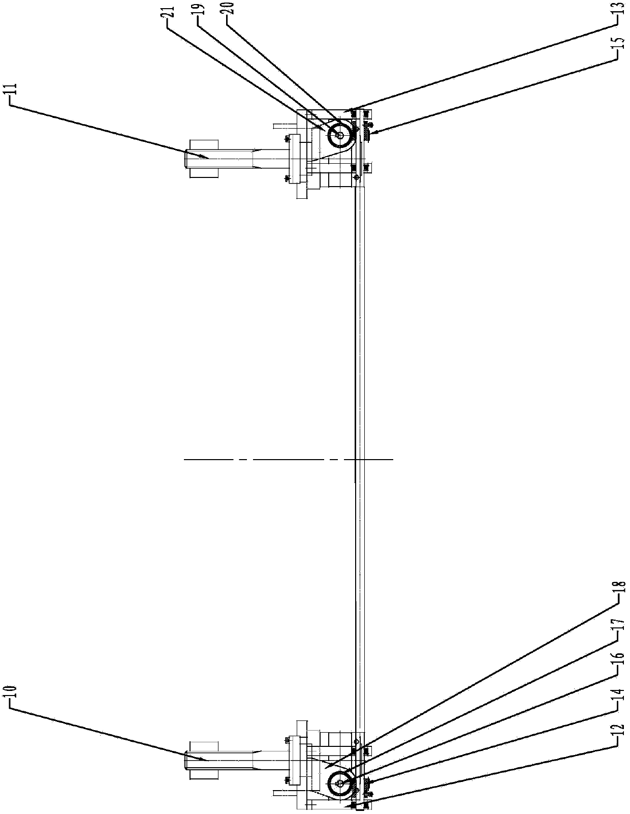
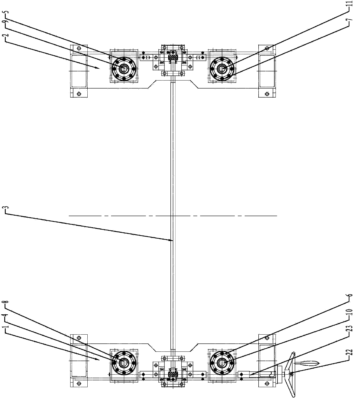
[0013] like Figures 1~3 As shown, the present invention mainly includes a synchronizing link 3, and both ends of the synchronizing link 3 are connected to the first frame 1 and the second frame 2 through the first synchronizing link seat 12 and the second synchronizing link seat 13 respectively. Two ends of the synchronizing link 3 are respectively connected with the first synchronizing gear 14 and the second synchronizing gear 15 .
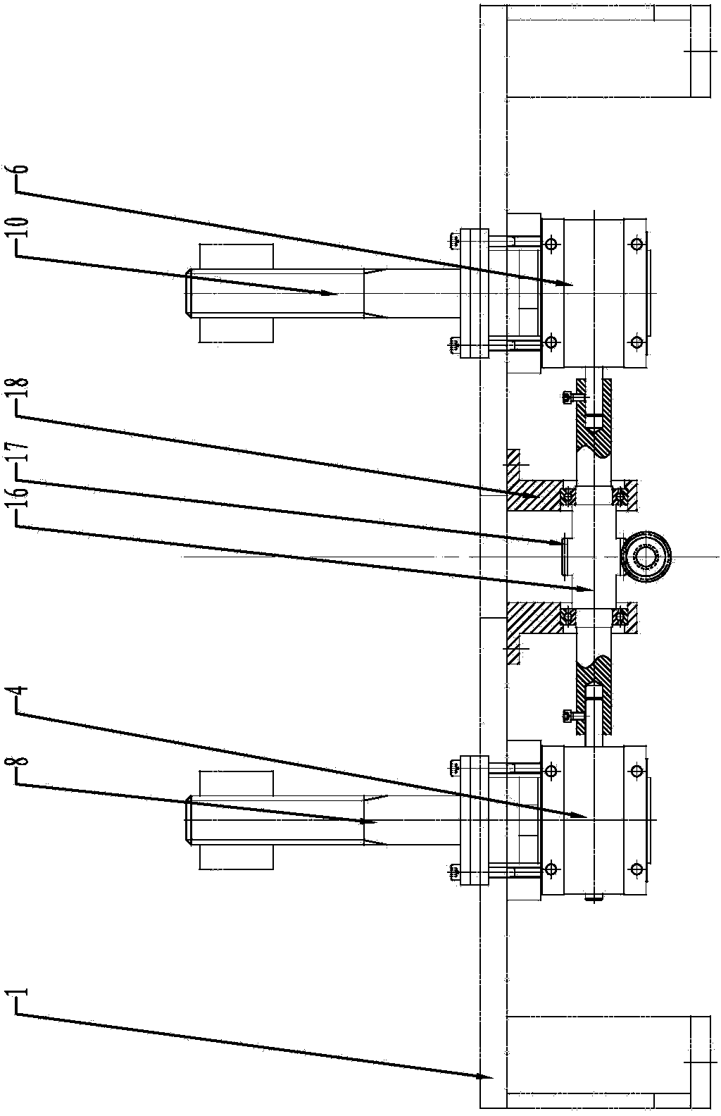
[0014] The first frame 1 is symmetrically provided with a first reducer 4 and a third reducer 6, the first reducer 4 and the third reducer 6 are connected by a first transmission link 16, and both ends of the first transmission link 16 pass through The first transmission link seat 18 is connected to the first frame 1 . A first helical gear 17 is provided in the middle of the first transmission link 16 , and the first helical gear 17 is meshed with the first synchronizing gear 14 .
[0015] The second frame 2 is symmetrically provided with a second reducer 5 and a fourth reducer 7, the second reducer 5 and the fourth reducer 7 are connected by a second transmission link 19, and both ends of the second transmission link 19 pass through The second transmission link seat 21 is connected to the second frame 2 . A second helical gear 20 is provided in the middle of the second transmission link 19 , and the second helical gear 20 is meshed with the second synchronizing gear 15 .
[0016] The input end of the third reducer 6 is connected to the handwheel connecting rod 23 , and the handwheel connecting rod 23 is connected to the handwheel 22 .
[0017] The upper end of the first reducer 4 is connected with a first lifting screw 8 , and the first lifting screw 8 is connected with a first lifting screw sleeve.
[0018] The upper end of the second reducer 5 is connected with a second lifting screw 9 , and the second lifting screw 9 is connected with a second lifting screw sleeve.
[0019] The upper end of the third reducer 6 is connected with a third lifting screw 10 , and the third lifting screw 10 is connected with a third lifting screw sleeve.
[0020] The upper end of the fourth reducer 7 is connected with a fourth lifting screw 11 , and the fourth lifting screw 11 is connected with a fourth lifting screw sleeve.
[0021] The working process of the present invention is as follows: when working, the rotating handwheel 22 drives the handwheel connecting rod 23 to rotate, and the handwheel connecting rod 23 transmits the transmission to the first reducer 4 and the first transmission connecting rod 16 through the third reducer 6 , the first elevating screw 8 and the third elevating screw 10 on the first reducer 4 and the third reducer 6 rotate accordingly, thereby driving the welding devices on the first elevating screw sleeve and the third elevating screw sleeve Synchronized lift. The first transmission link 16 drives the synchronization link 3 to rotate through the first synchronization gear 14 meshing with the first helical gear 17, thereby transmitting the power to the second reducer 5 and the fourth reducer 7, and driving the second lifting screw 9 and the fourth lifting screw 11 rotate, thereby driving the welding device on the second lifting screw sleeve and the fourth lifting screw sleeve to rise and fall synchronously.

PUM

no PUM

Description & Claims & Application Information

We can also present the details of the Description, Claims and Application information to help users get a comprehensive understanding of the technical details of the patent, such as background art, summary of invention, brief description of drawings, description of embodiments, and other original content. On the other hand, users can also determine the specific scope of protection of the technology through the list of claims; as well as understand the changes in the life cycle of the technology with the presentation of the patent timeline. Login to view more.

Similar technology patents

Biometric identification apparatus

InactiveUS20080037001A1perform accurately and rapidlysimple structure
Owner:HITACHI MEDIA ELECTORONICS CO LTD

Fuel cell

ActiveUS20070207372A1simple structuremaintain durability
Owner:HONDA MOTOR CO LTD

Isolation implant in abdominal aorta external and internal iliac artery cavity

Owner:SECOND MILITARY MEDICAL UNIV OF THE PEOPLES LIBERATION ARMY

Classification and recommendation of technical efficacy words

  • Simple structure

Sharing system for air-conditioning coat

InactiveCN107440179ASimple structureeasy to wear
Owner:QINGDAO HAIER AIR CONDITIONER GENERAL CORP LTD

Emergency parachuting device and method for multiple-rotor unmanned aerial vehicle

InactiveCN103895870Aavoid aircraft crashSimple structure
Owner:SOUTH CHINA AGRI UNIV +1

Quick pipe connector

Owner:YANG RICHARD

Automatic washing and dewatering combined device of rotary type mop

InactiveCN102370447Areduce volumeSimple structure
Owner:上海祥美网络科技有限公司 +1
Why Eureka
Try Eureka