Fixing ring

A fixed ring and sheet technology, applied in the field of fixed rings, can solve problems such as the failure to know the damage of the fixed ring in time, economic loss, wafer damage, etc.

Active Publication Date: 2013-12-04
SHANGHAI HUALI MICROELECTRONICS CORP
View PDF7 Cites 3 Cited by
  • Summary
  • Abstract
  • Description
  • Claims
  • Application Information

AI Technical Summary

Problems solved by technology

[0004] The present invention provides a fixed ring to solve the problem that the damage of the existing fixed ring cannot be known in time, resulting in economic loss caused by wafer damage

Method used


Image

  • Fixing ring
  • Fixing ring
  • Fixing ring

Examples


Embodiment Construction

[0014] In order to describe the technical solution of the above invention in more detail, specific examples are listed below to demonstrate the technical effect; it should be emphasized that these examples are used to illustrate the present invention and not limit the scope of the present invention.

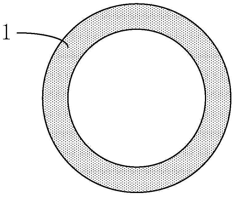
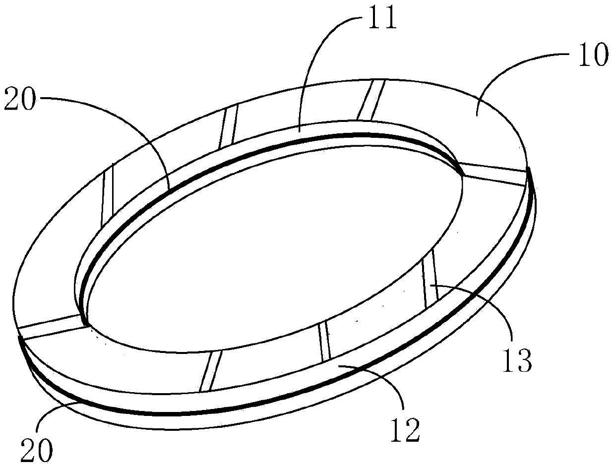
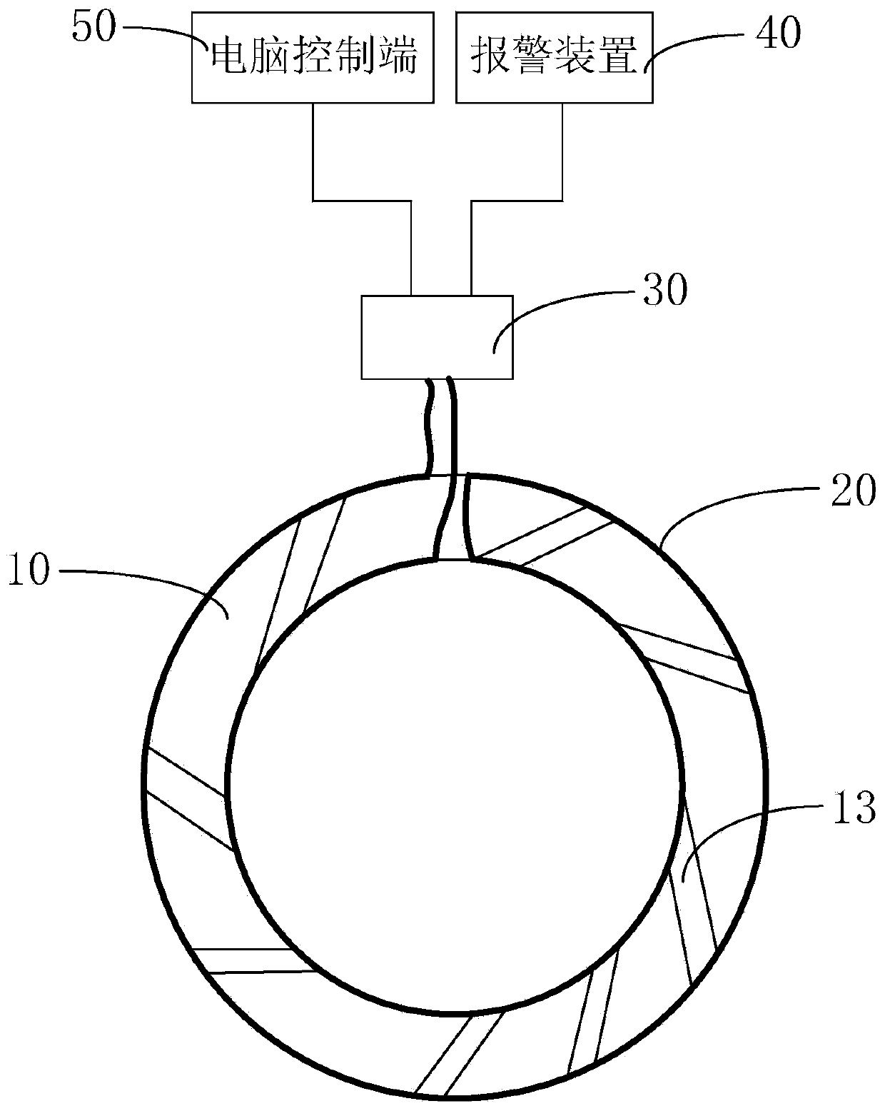
[0015] The fixed ring provided by the present invention, such as Figures 2 to 3 As shown, it includes a sheet-shaped ring 10, and also includes a wire 20, a pulse current signal sensor 30 and an alarm device 40. The wire 20 is arranged on the inner wall 11 and the outer wall 12 of the thin-shaped ring 10. Of course, the wire 20 The arrangement is not limited to image 3 The winding method shown is sufficient as long as it can achieve the technical effect that the wire 20 will be broken if the sheet-shaped ring 10 is damaged. Both ends of the wire 20 are respectively connected to the input end of the pulse current signal sensor 30 , and the output end of the pulse current signal...


PUM


Abstract

The invention relates to a fixing ring, comprising a thin slice type ring, a conductive wire, a pulse current signal sensor and a warning device, wherein the conductive wire is arranged on the inner wall and the outer wall of the thin slice type ring; two ends of the conductive wire are connected with the input end of the pulse current signal sensor respectively; the output end of the pulse current signal sensor is connected to the warning device. According to the fixing ring, the conductive wire is arranged on the inner wall and the outer wall of the thin slice type ring, and the two ends of the conductive wire are connected to the input end of the pulse current signal sensor; therefore, when the thin slice type ring is intact, the pulse current signal sensor receives a normal pulse current signal through the conduction function of the conductive wire, and the fixing ring works normally; when the thin slice type ring is damaged, the conductive wire fails to conduct; the pulse current signal sensor receives no normal signal so as to output a warning signal to the warning device; the warning device warns an operator of the damage and calls for the timely-replacement of the fixing ring; therefore, the potential risks and economic losses caused by the damage of the fixing ring are effectively lowered.

Description

technical field [0001] The invention relates to the field of chemical mechanical polishing, in particular to a fixed ring capable of automatic alarm. Background technique [0002] With the development of semiconductor manufacturing technology, while the critical dimensions of integrated circuits are getting smaller and smaller, the size of wafers is getting bigger and bigger, and the value of single wafers is getting higher and higher. Therefore, in the process of wafer processing Once fragmentation occurs, the economic loss brought to the factory is also increasing. There are many factors that cause wafer fragmentation during processing. Among them, the fracture of the fixed ring on the polishing head during the polishing process is one of the factors that cause wafer fragmentation. If the fracture of the fixed ring cannot be detected in time and Stopping the operation of the polishing machine will not only cause wafer fragmentation, but may even cause serious damage to ot...

Claims


Application Information

Patent Timeline
IPC IPC(8): B24B37/32G01N27/00
Inventor 李虎张守龙白英英陈玉文
Owner SHANGHAI HUALI MICROELECTRONICS CORP
Why Eureka
Try Eureka