
Paper cutting device of printer

A paper cutting device and printer technology, applied in metal processing, etc., can solve the problems of contact wear between the moving knife and the fixed knife surface, small paper cutting ability, and short service life, so as to improve working capacity, prolong service life, and reduce wear Effect

Active Publication Date: 2013-12-04
JIANGMEN DASCOM COMP PERIPHERAL
View PDF8 Cites 2 Cited by
  • Summary
  • Abstract
  • Description
  • Claims
  • Application Information

AI Technical Summary

Problems solved by technology

The first is the plane knife paper cutting structure. The structure is that the cutting edge of the moving knife and the fixed knife are in plane contact when cutting and withdrawing the knife. The knife and the fixed knife are prone to surface contact wear, and the service life is short. In addition, the installation and coordination precision of the moving knife and the fixed knife is required to be high; the second is the rotary paper cutter structure, which mainly uses a motor to The rotary cutting is driven by a gear set or a combination of worm gear and worm. The moving knife and the fixed knife are in point contact during the cutting and retracting process. The pressing force between the moving knife and the fixed knife is very small, so the wear of the moving knife and the fixed knife Reaching the minimum, the tool life is longer, but the paper cutting capacity of this paper cutting structure is small, it is difficult to cut thick paper, because the static distance between the moving knife and the fixed knife is small, it is easy to jam the paper higher

Method used


Image

  • Paper cutting device of printer
  • Paper cutting device of printer
  • Paper cutting device of printer

Examples


Embodiment Construction

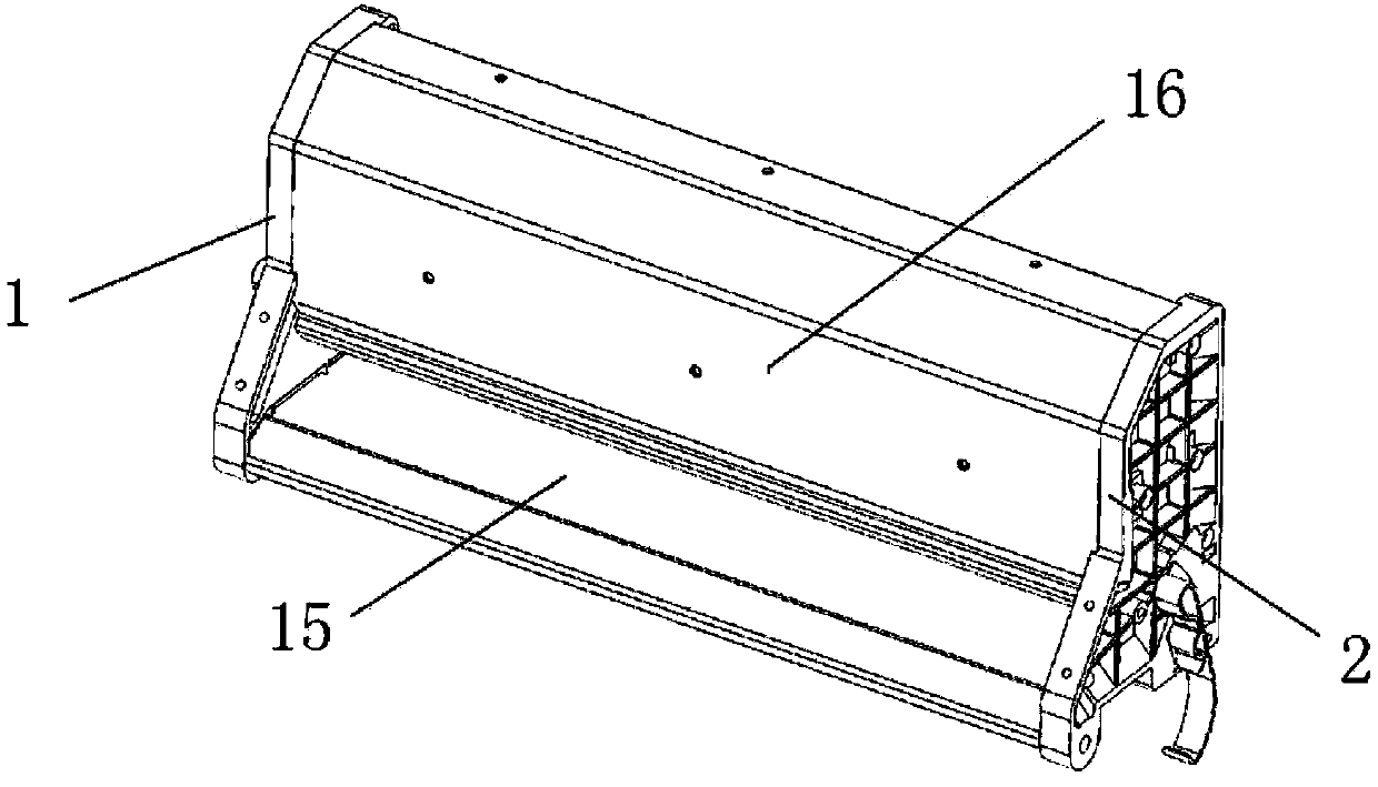
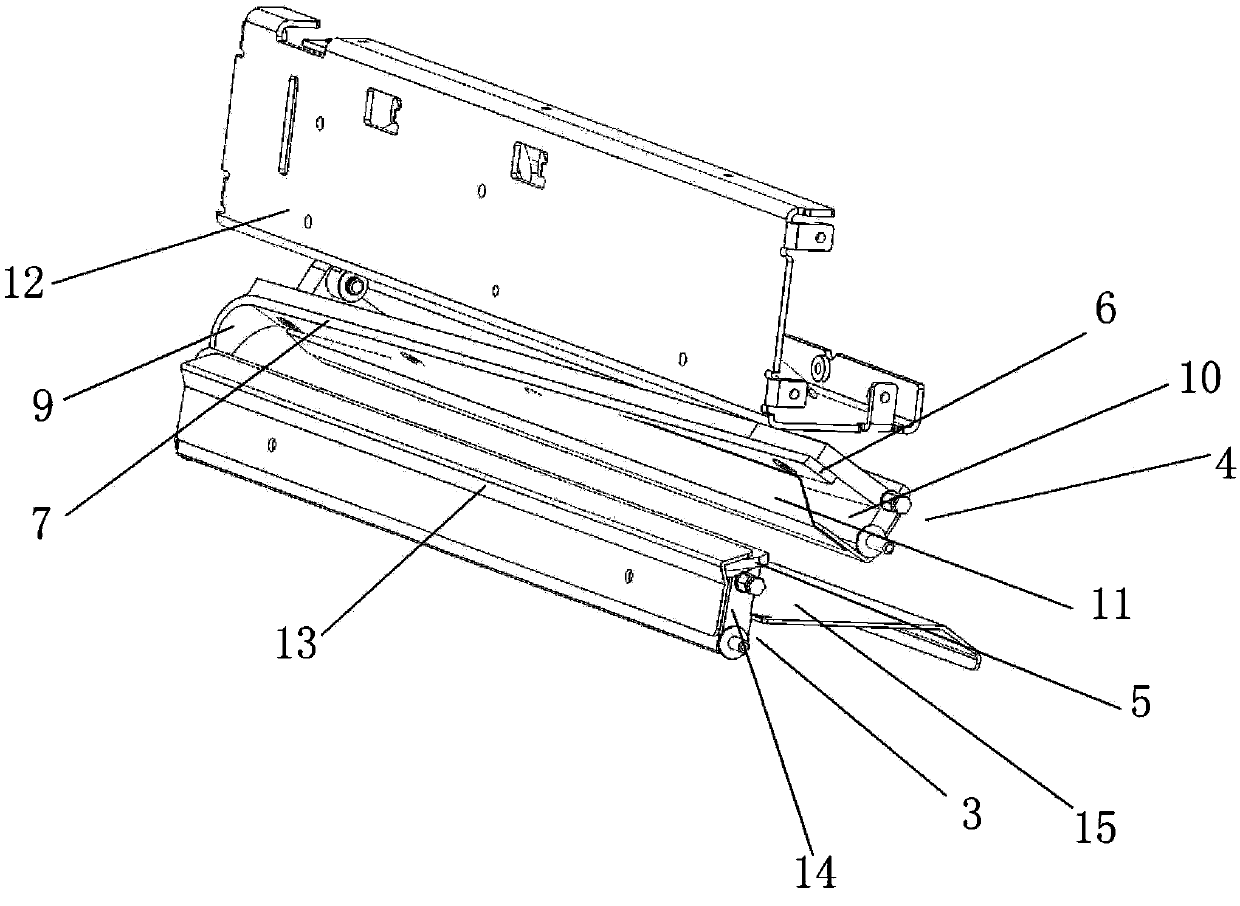
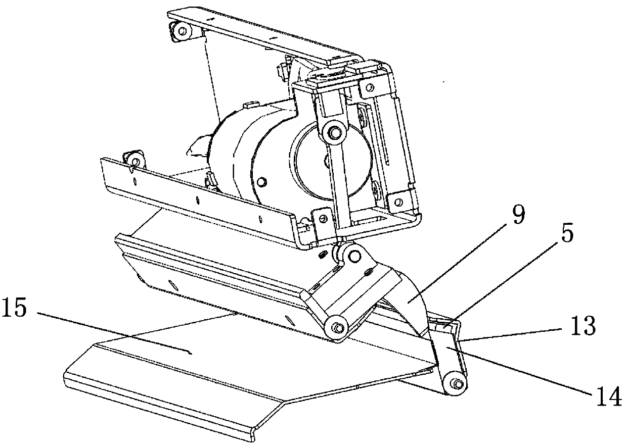
[0019] refer to figure 1 , figure 2 and image 3 , a paper cutting device for a printer of the present invention comprises left and right cutter brackets 1 and 2, and a fixed knife group 3 and a moving knife group 4 that cooperate with each other are respectively installed on the left and right cutter brackets 1 and 2, said A fixed blade 5 is installed on the fixed knife group 3, and the two ends of the movable knife group 4 are pivotally connected with the left and right cutter brackets 1 and 2 respectively, and the swing end of the movable knife group 4 is equipped with a corresponding matching blade 5. The movable blade 6, the movable blade 7 of the movable blade is laterally inclined, the fixed blade 5 has a fixed blade 8, the lateral projection of the movable blade coincides with the lateral projection of the fixed blade, wherein the lateral projection of the movable blade is arc-shaped, Its center of circle coincides with the center of the pivot joint at the two ends ...


PUM


Abstract

The invention discloses a paper cutting device of a printer. The paper cutting device comprises a left cutter support and a right cutter support, wherein a fixed cutter group and a movable cutter group which are matched are installed on the left cutter support and the right cutter support respectively, a fixed blade is installed on the fixed cutter group, two ends of the movable cutter group are in pivot joint with the left cutter support and the right cutter support respectively, a movable blade correspondingly matched with the fixed blade is installed at the swing end of the movable cutter group, and the movable blade edge of the movable blade is arranged transversely and obliquely. The fixed blade is provided with the fixed blade edge, the transverse projection of the movable blade coincides with the transverse projection of the fixed edge, the transverse projection of the movable blade is circular-arc-shaped, and the circle center of the transverse projection coincides with the pivot joint center of the two ends of the movable cutter group. The working capacity of the paper cutting device of the printer is improved, a paper stuck phenomenon during paper outputting is avoided, the movable blade and the fixed blade always adhere in the swing cutting process of the movable cutter group, and the cutting effect is ensured. In addition, the danger of cutter bumping is avoided, the blade abrasion is reduced, and the service life of the paper cutting device is prolonged.

Description

technical field [0001] The invention relates to a printer auxiliary device, in particular to a printer paper cutting device. Background technique [0002] With the development of modernization in our country, self-service equipment is gradually adopted in various industries, such as instrumentation, supermarkets, convenience stores, postal services, banks, tobacco monopoly, utility meter reading, mobile police system, mobile government affairs system, etc. Printers on kiosks must have an automatic paper cutter. At present, the paper cutting structure of the printer is generally divided into two types. The first is the plane knife paper cutting structure. The structure is that the cutting edge of the moving knife and the fixed knife are in plane contact when cutting and withdrawing the knife. The knife and the fixed knife are prone to surface contact wear, and the service life is short. In addition, the installation and coordination precision of the moving knife and the fix...

Claims


Application Information

Patent Timeline
IPC IPC(8): B26D1/30B26D7/26
Inventor 汤锡堂张展伟
Owner JIANGMEN DASCOM COMP PERIPHERAL
Features
  • Generate Ideas
  • Intellectual Property
  • Life Sciences
  • Materials
  • Tech Scout
  • Unparalleled Data Quality
  • Higher Quality Content
  • 60% Fewer Hallucinations
Learn More