Material conveying device

A technology for conveying devices and materials, applied in the direction of conveyors, conveyor objects, transportation and packaging, etc., it can solve the problems that it is difficult to meet the requirements of material feeding, affect the efficiency of material processing, and the materials cannot be transported centrally, so as to improve the conveying efficiency, Ease of concentration and simple structure

Active Publication Date: 2013-12-04
ZHANGJIAGANG XIAFEI PLASTIC
View PDF5 Cites 6 Cited by
  • Summary
  • Abstract
  • Description
  • Claims
  • Application Information

AI Technical Summary

Problems solved by technology

[0002] There are many forms of material conveying, among which the belt conveying structure is the most commonly used, but it is difficult to meet the feeding requirements for different product belt conveying structures, for example, perfume bottle caps, nozzles, etc., during the feeding process, The bottle caps and nozzles are loaded in batches, which are easy to fall off from both sides of the belt, resulting in the inability of the materials to be conveyed on the belt. At the same time, when they are conveyed to the processing area, the materials are also scattered, which is not conducive to the feeding of processing equipment. , which directly affects the efficiency of material processing

Method used


Image

  • Material conveying device
  • Material conveying device

Examples


Embodiment Construction

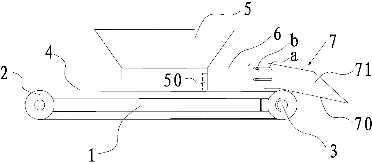
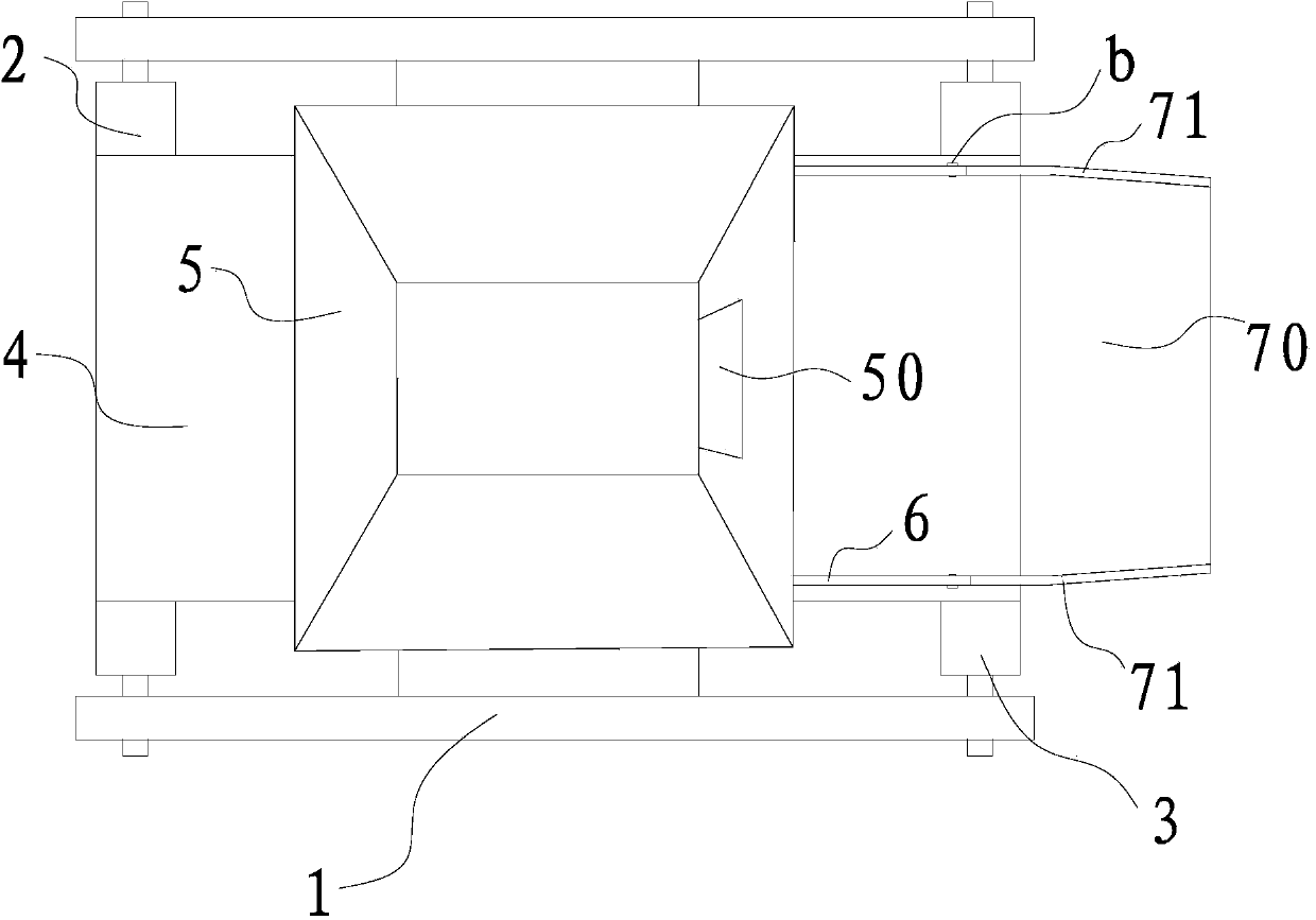
[0017] Such as figure 1 and figure 2 As shown, a material conveying device provided in this embodiment includes a first roller shaft 2 and a second roller shaft 3 that are respectively arranged at both ends of the frame 1 and can rotate around their own axes. The conveyor belt 4 on the first roller shaft 2 and the second roller shaft 3, and the driving mechanism (not shown) that drives the first roller shaft 2 or the second roller shaft 3 to rotate, meanwhile, the conveying device in this example also includes The hopper 5 arranged above the conveyor belt 4 between the first roller shaft 2 and the second roller shaft 3, along the conveying direction of the conveyor belt 4 and the baffle plates 6 arranged on both sides of the hopper 5, wherein the hopper 5 is arranged on On the frame 1, and the direction of the discharge port 50 of the hopper 5 is consistent with the conveying direction of the conveyor belt 4, the material retaining plate 6 is connected to both sides of the d...


PUM


Abstract

The invention discloses a material conveying device, which comprises a first roll shaft, a second roll shaft, a conveying belt, a driving mechanism, a hopper and material-blocking plates, wherein the first roll shaft and the second roll shaft are respectively arranged at two ends of a rack and can rotate around the self shaft axes; the conveying belt is sheathed on the first roll shaft and the second roll shaft; the driving mechanism drives the first roll shaft or the second roll shaft to rotate; the hopper is arranged above the conveying belt arranged between the first roll shaft and the second roll shaft; and the material-blocking plates are arranged at two sides of the hopper along the conveying direction of the conveying belt. The hopper is arranged on the rack, and the direction of the discharge port of the hopper and the conveying direction of the conveying belt are consistent. The material-blocking plates are connected to two sides of the discharge port, and one end parts of the material-blocking plates of the two sides are respectively connected onto the hopper. Due to the hopper and the material-blocking plates, the material concentration is convenient, the phenomenon that the materials are easily spilled from the two sides of the conveying belt is reduced, and the conveying efficiency of materials is increased. Meanwhile, the conveying device has the advantages of simple structure and convenience in implementation.

Description

technical field [0001] The invention relates to a material conveying device. Background technique [0002] There are many forms of material conveying, among which the belt conveying structure is the most commonly used, but it is difficult to meet the feeding requirements for different product belt conveying structures, for example, perfume bottle caps, nozzles, etc., during the feeding process, Bottle caps and nozzles are fed in batches, which are easy to fall off from both sides of the belt, resulting in the inability of the materials to be conveyed on the belt in a concentrated manner. At the same time, when they are conveyed to the processing area, the materials are also scattered, which is not conducive to the feeding of processing equipment. , which directly affects the efficiency of material processing. Contents of the invention [0003] The technical problem to be solved by the present invention is to overcome the deficiencies of the prior art and provide an improv...

Claims


Application Information

Patent Timeline
Patent Type & Authority Applications(China)
IPC IPC(8): B65G47/18B65G21/20
Inventor 徐岳年
Owner ZHANGJIAGANG XIAFEI PLASTIC
Why Eureka
Try Eureka