Placement structure of vacuum glass getter and method of making the same

A technology of vacuum glass and getter, which is applied in the field of vacuum glass to achieve the effects of high vacuum degree, improved production efficiency and qualified rate, and low cost

Active Publication Date: 2016-03-30
戴长虹
View PDF3 Cites 1 Cited by
  • Summary
  • Abstract
  • Description
  • Claims
  • Application Information

AI Technical Summary

Problems solved by technology

[0004] The technical problem to be solved by the present invention is to provide a new type of vacuum glass getter placement structure and its manufacturing method for the defects of the existing vacuum glass getter placement structure. The manufacturing method of the placement structure is simple, and the vacuum glass produced, including the tempered vacuum glass, can overcome the deficiency of the getter in the prior art, effectively ensure the high vacuum degree of the vacuum layer of the vacuum glass, prolong the service life of the vacuum glass, and It can improve the production efficiency of vacuum glass containing getter and reduce the production cost

Method used


Image

  • Placement structure of vacuum glass getter and method of making the same
  • Placement structure of vacuum glass getter and method of making the same

Examples


Embodiment 1

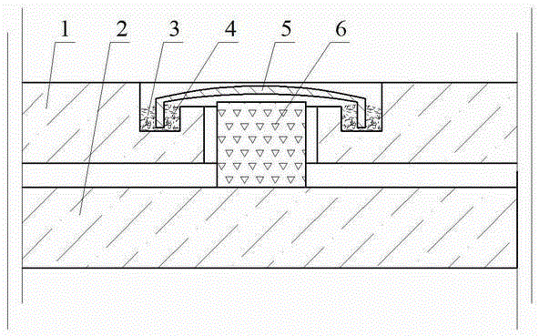
[0059] Embodiment 1: see figure 1 , the vacuum glass is made up of upper glass 1 and lower glass 2, a through hole is drilled on the upper glass 1 to form a suction port, and a U-shaped sealing groove 4 concentric with the suction port is made by a hollow drill on the upper surface of the upper glass 1, and sealed The inner edge of the groove 4 is lower than the upper surface of the upper glass 1; a sealing cover 5 is made according to the size of the sealing groove 4, and the edge of the sealing cover 5 can be inserted in the sealing groove 4, and the height of the sealing cover 5 is lower than that of the upper glass 1 The upper surface of the upper surface of the sealing cover 5 and the sealing groove 4 is an air extraction channel; the inner surface of the sealing groove 4 is coated with metal paste, and then sent into a tempering furnace to temper the upper and lower glass, or directly use low-temperature glass solder in the normal Edge sealing is carried out on the upper...

Embodiment 2

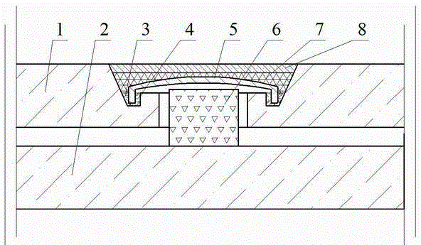
[0060] Example 2: see figure 2 , basically the same as in Example 1, the difference is that the sealing groove 4 is changed into a V-shaped groove, the metal solder 3 is changed into a zinc alloy, and the metal solder 3 is condensed into a solid to realize airtight sealing of the air inlet, and then the vacuum heating furnace is opened. Take out the vacuum glass. Put into the sealant 7 such as butyl glue in the suction port while it is hot, the top of the sealant 7 covers the product trademark 8, and the trademark 8 is flush with the upper surface of the upper glass 1.


PUM


Abstract

An accommodating structure of vacuum glass getter is characterized in that a hole is formed in the upper glass of vacuum glass so as to form an extraction opening; a sealed groove is formed in the upper surface of the upper glass and in a position at the periphery of the extraction opening; a sealing cover is arranged on the sealed groove; the edge part of the sealing cover is inserted into the sealed groove; after the edges of the upper glass and lower glass are sealed, the vacuum glass getter is put into the extraction opening; the sealing cover is closed; metal solder is put into the sealed groove or onto the sealing cover; vacuum pumping and heating are perform at the extraction opening; the vacuum glass getter is activated automatically under the conditions of high temperature and high vacuum while the metal solder is molten into liquid due to high temperature; the liquid is kept in the sealed groove; the edge part of the sealing cover is immersed in the liquid; the extraction opening is sealed automatically according to the liquid seal principle; the vacuum glass getter is sealed in a vacuum layer; after temperature reduction, the liquid freezes, so as to realize airtightness sealing. According to the manufacture method provided by the invention, mass production can be realized, the production efficiency and qualification rates of vacuum glass can be greatly improved, and the manufacturing cost of the vacuum glass is lowered.

Description

technical field [0001] The invention belongs to the field of vacuum glass, and in particular relates to a placement structure of a vacuum glass getter and a manufacturing method thereof. Background technique [0002] The existing vacuum glass is generally composed of two or three pieces of flat glass. The glass is sealed with low-temperature glass solder around the edges, and there is a tiny support in the middle. A thin layer of 0.1-0.2mm thickness is formed between the two pieces of glass by pumping air. Vacuum layer. Since there is no heat and sound transmission of gas, and the inner surface of the glass can have a transparent low-heat radiation film, the vacuum glass has good heat insulation and sound insulation effects, and is one of the best performance energy-saving glasses. [0003] The key technologies of the existing vacuum glass include: one is edge sealing, the other is the placement of supports, and the third is the acquisition and maintenance of vacuum. The m...

Claims


Application Information

Patent Timeline
Patent Type & Authority Patents(China)
IPC IPC(8): C03C27/08
Inventor 戴长虹
Owner 戴长虹
Why Eureka
Try Eureka