
Continuous box girder adopting corrugated steel web steel structure

A corrugated steel web and steel structure technology, applied in truss structures, joists, girders, etc., can solve the problems of short service life of box girder, poor shear and buckling resistance, and stress concentration.

Active Publication Date: 2013-12-04
ZHEJIANG CTB WAVEFORM STEEL WEB
View PDF8 Cites 2 Cited by
  • Summary
  • Abstract
  • Description
  • Claims
  • Application Information

AI Technical Summary

Problems solved by technology

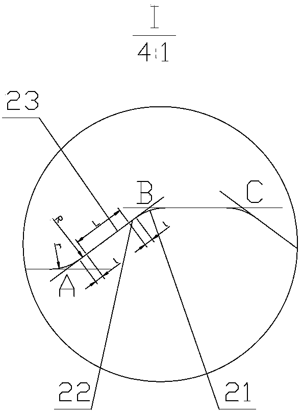
[0003] The present invention aims at the disadvantages of poor shear resistance and buckling resistance of ordinary box girders in the prior art, and the corrugated steel webs of box girders are prone to stress concentration, resulting in short service life of the box girder, etc., and provides a method by setting The end plate of the head can improve the cross-sectional rigidity of the beam body and the strength of the connection end. The waveform of the web plate is composed of three parts: a straight line section, a transition section, and an arc section. The transition section can effectively connect the straight line section and the arc section to solve the problem. The problem of stress concentration when the straight line section and the arc section are directly connected, the inserted pressure bearing structure in the compression area can not only make the connection stable, but also have shrinkage space when the temperature changes, while the connection of the tension area is stable, the cavity Set up a continuous box girder with corrugated steel webs and steel structures that can resist thermal expansion and contraction when the temperature of the beam body changes

Method used


Image

  • Continuous box girder adopting corrugated steel web steel structure
  • Continuous box girder adopting corrugated steel web steel structure
  • Continuous box girder adopting corrugated steel web steel structure

Examples


Embodiment 1

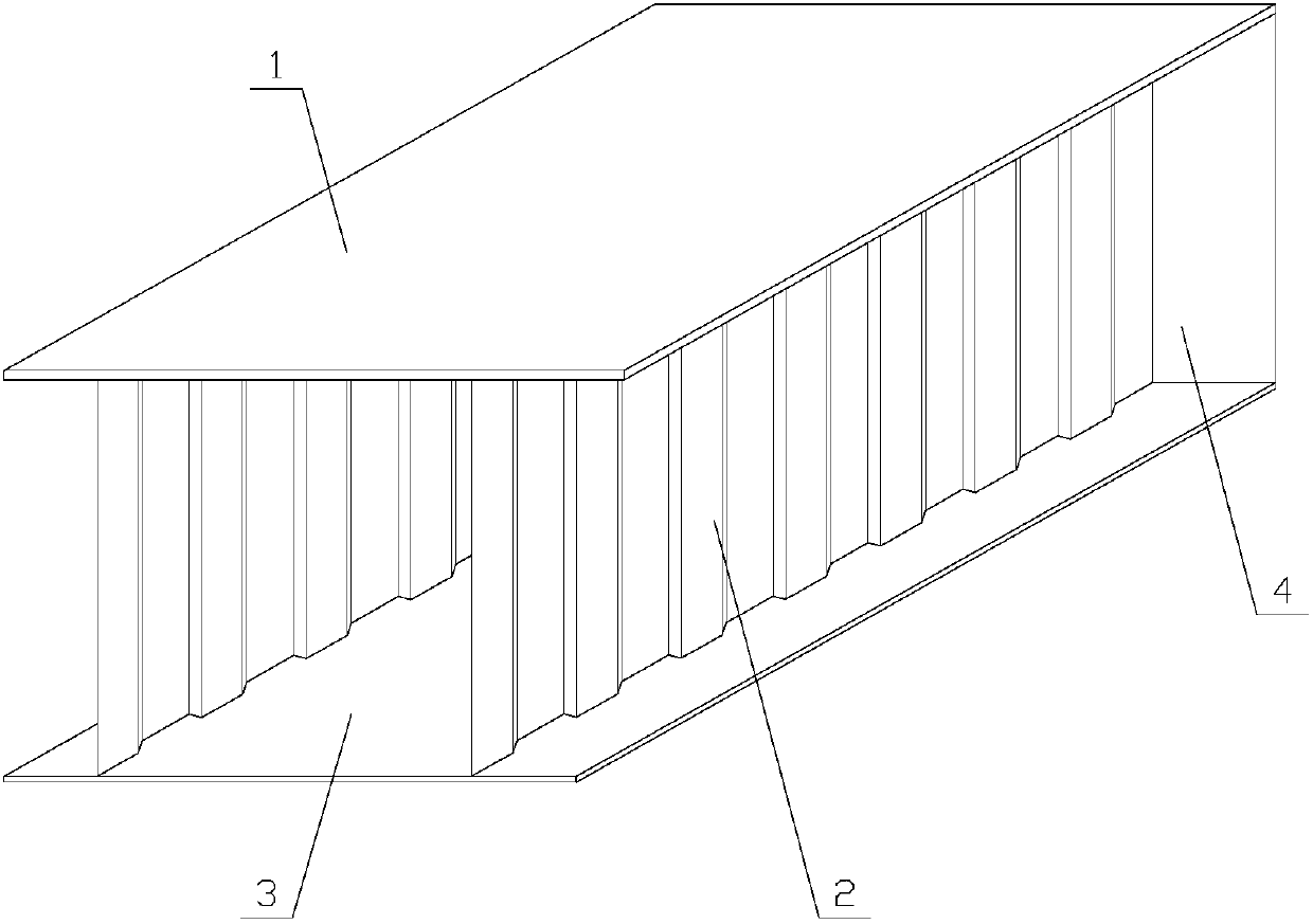
[0028] Corrugated steel web steel continuous box girder, such as Figure 1 to Figure 6 As shown, it includes two corrugated steel webs 2, a top steel plate 1, a bottom steel plate 3, and a connecting end. The corrugated steel web 2 is arranged between the top steel plate 1 and the bottom steel plate 3, and the top steel plate 1 and the corrugated steel web The plate 2 is connected by welding, the corrugated steel web 2 and the bottom steel plate 3 are connected by welding, and the individual beam structures are connected by connecting ends to form a continuous beam structure.

[0029] The surface roughness of the top steel plate and the bottom steel plate is 70-350 μm. Increase the surface roughness of the top steel plate 1 and the bottom steel plate 3, high roughness can significantly increase the adhesion of the coating.

[0030] The corrugated steel web is a continuous trapezoidal corrugated steel plate with a transition section and an arc corner. The transition section is...

Embodiment 2

[0038] Such as Figure 1 to Figure 5 , 7, the difference between this embodiment and embodiment 1 is that the single beam structures are connected by steel cables 5 to form a continuous beam structure. The compression area of ​​the connection end is a plug-in structure. The plug-in structure is that one end of the connection end of the box girder is provided with a plug 24, and the other end is provided with a jack 25. The adjacent simply supported box girders are connected through the plug 24 and the jack 25. . Through the cooperation of the plug 24 and the socket 25, the plug-in pressure-bearing structure of the pressure-receiving area can not only make the connection stable, but also have shrinkage space when the temperature changes. While the connection of the tension area is stable, the setting of its cavity can resist the phenomenon of thermal expansion and contraction when the temperature of the beam body changes.

[0039] The plug 24 is provided with a barb, and the ...


PUM

PropertyMeasurementUnit
surface roughnessaaaaaaaaaa

Abstract

The invention relates to a box girder, particularly to a continuous box girder adopting a corrugated steel web steel structure, which includes two or more corrugated steel webs, a top steel plate, a bottom steel plate and a connecting end, wherein the corrugated steel webs are arranged between the top steel plate and the bottom steel plate; the top steel plate is connected with the corrugated steel webs through welding; and the bottom steel plate is connected with the corrugated steel webs through welding; the single girder body structure forms a continuous girder structure through the connecting end or steel nooses or the combined connection of the connecting end and the steel nooses. The wave forms of the webs in the continuous box girder include three parts, namely the straight line section, the transitional section and the arc section, the transitional sections can be used for effectively connecting the straight line sections with arc corners, thereby solving the problem of stress concentration during the direct connection of the straight line sections and the arc sections, an inserting-type pressure-bearing structure in a pressure-bearing zone enables the connection to be stable, is provided with a shrinking space in case of temperature variation, and is stable in the connection of a pulled zone, and the arranged cavity can be used for resisting thermal expansion when the temperature of the girder body varies.

Description

technical field [0001] The invention relates to a box girder, in particular to a corrugated steel web steel structure continuous box girder. Background technique [0002] At present, traditional I-beam box girders or steel box girders generally have a web height-to-thickness ratio of about 100:1 according to the requirements of shear buckling resistance. The height-to-thickness ratio can reach 300:1 and above. For the corrugated steel web used in the existing corrugated steel web box girder, the corrugation of the web is composed of a straight line segment and an arc segment, and stress concentration is likely to occur at the connecting part of the straight line segment and the arc segment. Contents of the invention [0003] The present invention aims at the disadvantages of poor shear resistance and buckling resistance of ordinary box girders in the prior art, and the corrugated steel webs of box girders are prone to stress concentration, resulting in short service life ...

Claims


Application Information

Patent Timeline
Patent Type & Authority Applications(China)
IPC IPC(8): E04C3/07E01D19/00E01D2/04
Inventor 孙天明李强
Owner ZHEJIANG CTB WAVEFORM STEEL WEB
Learn More