
An iron driller support device adopting a telescopic support structure

A telescopic bracket and supporting device technology, applied in drill pipe, drill pipe, drilling equipment and other directions, can solve the problems of complex structure and large space occupation, and achieve the effect of saving space, small space occupation and simple structure

Active Publication Date: 2015-09-16
SHANXI NORTH MACHINE BUILDING
View PDF8 Cites 2 Cited by
  • Summary
  • Abstract
  • Description
  • Claims
  • Application Information

AI Technical Summary

Problems solved by technology

[0003] The purpose of the present invention is to provide an iron driller support device with a simple structure and a small space occupation for the disadvantages of the traditional iron driller support device such as complex structure and large space occupation

Method used


Image

  • An iron driller support device adopting a telescopic support structure
  • An iron driller support device adopting a telescopic support structure
  • An iron driller support device adopting a telescopic support structure

Examples


Embodiment

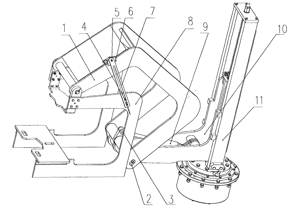
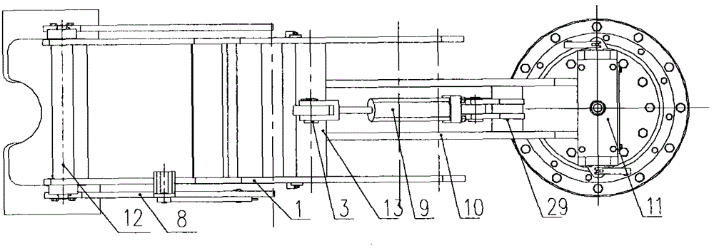
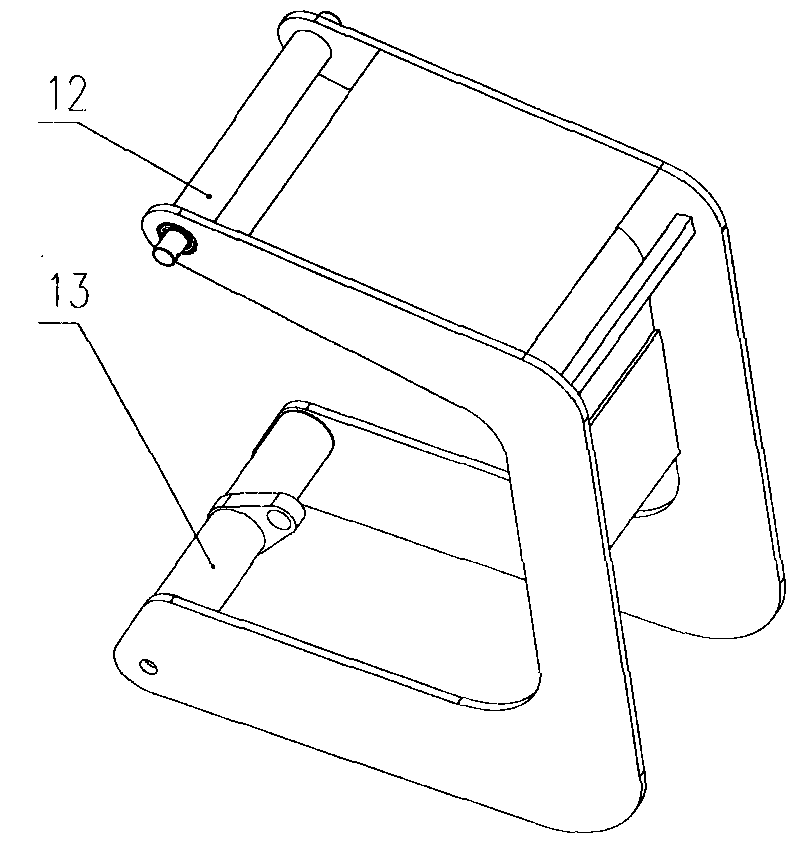
[0028] A kind of iron driller's support device adopting telescopic support structure of the present invention, as figure 1 As shown, it includes: telescopic support 1, leveling mechanism 7, support frame 8, telescopic oil cylinder 9, lifting support 10, vertical landing mechanism 11:

[0029] Such as image 3 As shown, the telescopic support 1 is a support plate with a U-shaped structure vertically fixed at both ends of two parallel support beams, and the fixed positions of the two parallel support beams are located at the opening ends of the two U-shaped support plates; the upper support beam The two ends of 12 pass through two U-shaped support plates, which are used as the rotating shaft connecting the telescopic support 1 and the support frame 8; The connecting shaft hole connected with the lifting bracket 10; wherein the outer U-shaped support plate is fixed with a leveling mechanism connecting frame 6 at the rear end of the upper supporting beam 12, and the leveling mech...


PUM


Abstract

The invention relates to an iron roughneck supporting device with a telescopic support structure and belongs to the technical field of iron roughnecks. The supporting device comprises a telescopic support, a leveling mechanism, a support frame, a telescopic oil cylinder, a lifting support and a vertical lifting mechanism. According to the supporting device, a well drilling product is clamped through a clamping device fixed at the front ends of two guide plates of the support frame, the telescopic support is controlled to rotate around a rotating shaft through the telescopic oil cylinder, and the shaft joint of the telescopic support and the support frame is controlled to have a displacement relative to the lifting support. A lifting oil cylinder in the vertical lifting mechanism controls a vertical height of a lifting sliding block on the lifting support so as to control a working mechanism connected with the front end of the lifting sliding block to perform vertical motion. The leveling mechanism enables the two guide plates at the front end of the support frame to the kept horizontal under the limiting effect on the support frame. The supporting device is simple in structure and small in occupied space, and horizontal and vertical movement of a supported mechanism can be achieved reliably.

Description

technical field [0001] The invention relates to an iron driller support device adopting a telescopic bracket structure, belonging to the technical field of iron drillers. Background technique [0002] At present, the support devices used in the field of iron drillers are mainly divided into arm type or floor type. The arm type support has disadvantages such as complex structure, high manufacturing cost, and unreliable hinges. The installation shape of the floor-standing iron driller is mainly rail-type. The body of the equipment has no telescopic function. It depends on its body sitting on the rail, and the equipment can move on the rail to adjust the working position. Due to the need to install bases, supports or lay tracks on the drilling platform, it takes up a lot of space, and the space of the drilling platform, especially the space of the offshore drilling platform, is relatively limited, which limits its use to a certain extent. Contents of the invention [0003] T...

Claims


Application Information

Patent Timeline
Patent Type & Authority Patents(China)
IPC IPC(8): E21B19/16
Inventor 王东育赵瑜齐明明李省恒王跃军刘娟李忠九
Owner SHANXI NORTH MACHINE BUILDING
Learn More