Fuel injector assembly

A fuel injector assembly and fuel injector technology, which is applied to machines/engines, fuel injection devices, engine components, etc., can solve problems such as incomplete solutions, reduce wear, reduce rebound phenomenon, and improve stability. and reliability effects

Active Publication Date: 2013-12-04
CHINA FIRST AUTOMOBILE
View PDF7 Cites 23 Cited by
  • Summary
  • Abstract
  • Description
  • Claims
  • Application Information

AI Technical Summary

Problems solved by technology

But still do not completely solve the common problem of existing control valve assembly

Method used


Image

  • Fuel injector assembly
  • Fuel injector assembly

Examples


Embodiment Construction

[0020] The present invention will be further described below in conjunction with specific drawings and embodiments.

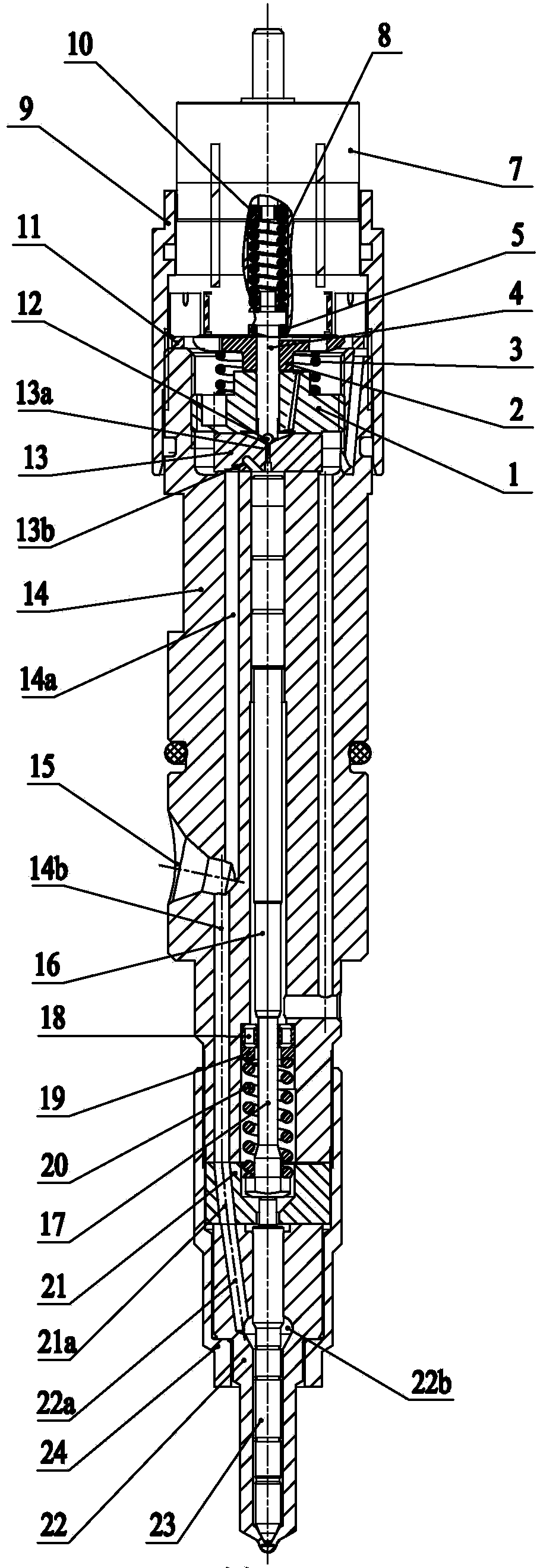
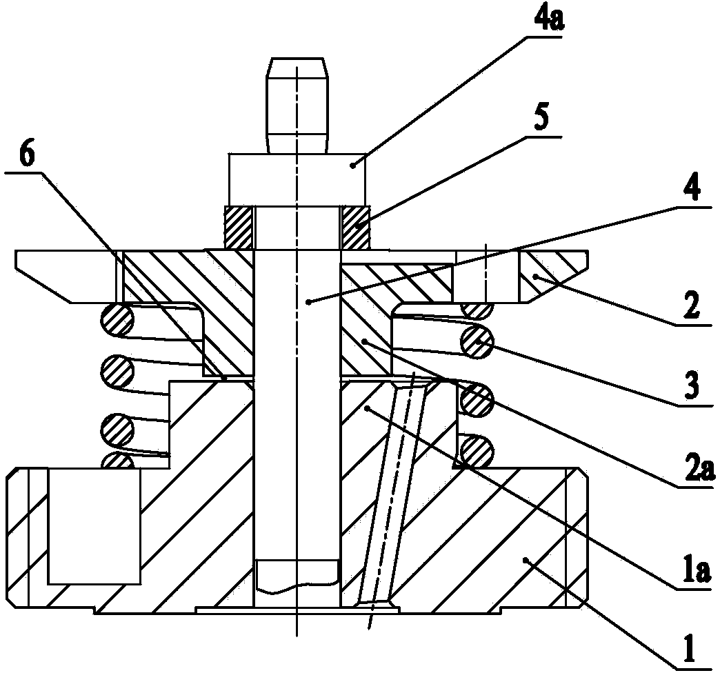
[0021] As shown in the figure: the fuel injector assembly in the embodiment is mainly composed of a control valve seat 1, an armature 2, a damping spring 3, an armature rod 4, a damping gasket 5, an armature damping gap 6, an electromagnet 7, and an electromagnet spring 8 , Electromagnet tight cap 9, Electromagnet gasket 10, Adjusting ring 11, Steel ball 12, Throttle orifice 13, Injector body 14, Control piston 16, Push rod 17, Spring upper seat 18, Adjusting gasket 19, Pressure regulating spring 20, transition block 21, fuel injector body 22, fuel injector needle valve 23, fuel injector tight cap 24 and other components.

[0022] Such as figure 1 , figure 2 As shown, the control valve assembly is installed in the concave cavity on the upper part of the injector body 14. The control valve assembly is mainly composed of a control valve seat 1, an armature 2 a...


PUM


Abstract

The invention relates to a fuel injector assembly comprising a control valve assembly, an electromagnet, an electromagnetic spring, an electromagnetic nut, a steel ball, a throttling orifice plate, a fuel injector body, a control piston, a push rod, an upper spring base, a pressure adjusting spring, a fuel nozzle coupling and a fuel nozzle nut. The fuel injector assembly is characterized in that an armature and an armature rod are of a split structure, the armature rod is sleeved with the armature in a movable mode, a damping spring is arranged between the lower end face of the armature and the upper end face of a control valve base, and the upper end face of the armature is connected with the armature rod through a limiting block arranged on the armature rod. Due to the fact that the armature and the armature rod are of the split structure, the control valve assembly greatly reduces falling impact force of a movable element when the control valve assembly is closed, stability and reliability in the closing process of a control valve are improved, the bounce-back phenomenon caused by falling impact of the movable element is reduced, abrasion in the closing process is reduced, and therefore performance of an engine is improved, service life of a common rail system in the engine is prolonged, and precise control of the injection process is facilitated.

Description

technical field [0001] The invention relates to a fuel injector assembly, in particular to a fuel injector assembly using a novel control valve assembly, and belongs to the technical field of engine fuel injection. Background technique [0002] The control valve assembly is an important component in the injector. In the prior art, the armature and the armature rod in the control valve assembly are integrated, and there is no damping under the armature. The moving parts in the control valve assembly with this structure have a large impact when seated, the components are severely worn, and there will be rebound phenomenon. The closing stability of the control valve is not good, and there will be wear and tear, which will affect the consistency of the fuel injection quantity. [0003] In order to reduce the seating impact of the moving parts in the control valve, some technical solutions are to add mechanical damping (that is, damping spring) or hydraulic damping (that is, hyd...

Claims


Application Information

Patent Timeline
Patent Type & Authority Applications(China)
IPC IPC(8): F02M51/06F02M61/06
Inventor 刘义亭庄福如俞建达王凌云蔡珍辉
Owner CHINA FIRST AUTOMOBILE
Why Eureka
Try Eureka