Vibrating fan

A fan and fan blade technology, applied in the field of vibrating fans, can solve the problems of reduced battery life, high power consumption, and cooling fans that are not suitable for portable devices, etc., to achieve the effects of improving life, reducing overall thickness, and avoiding loss

Active Publication Date: 2013-12-04
DELTA ELECTRONICS INC
View PDF7 Cites 9 Cited by
  • Summary
  • Abstract
  • Description
  • Claims
  • Application Information

AI Technical Summary

Problems solved by technology

Therefore, if a piezoelectric fan is installed in a portable device, it will consume a large amount of power and reduce battery life, so it is not suitable for use as a cooling fan for a portable device.

Method used


Image

  • Vibrating fan
  • Vibrating fan
  • Vibrating fan

Examples


Embodiment Construction

[0061] A number of embodiments of the present invention will be disclosed below with the accompanying drawings. For the sake of clarity, many practical details will be described together in the following description. However, those skilled in the art should appreciate that in some embodiments of the present invention, these practical details are not necessary and thus should not be used to limit the present invention. In addition, for the sake of simplifying the drawings, some conventional structures and elements will be shown in a simple and schematic manner in the drawings.

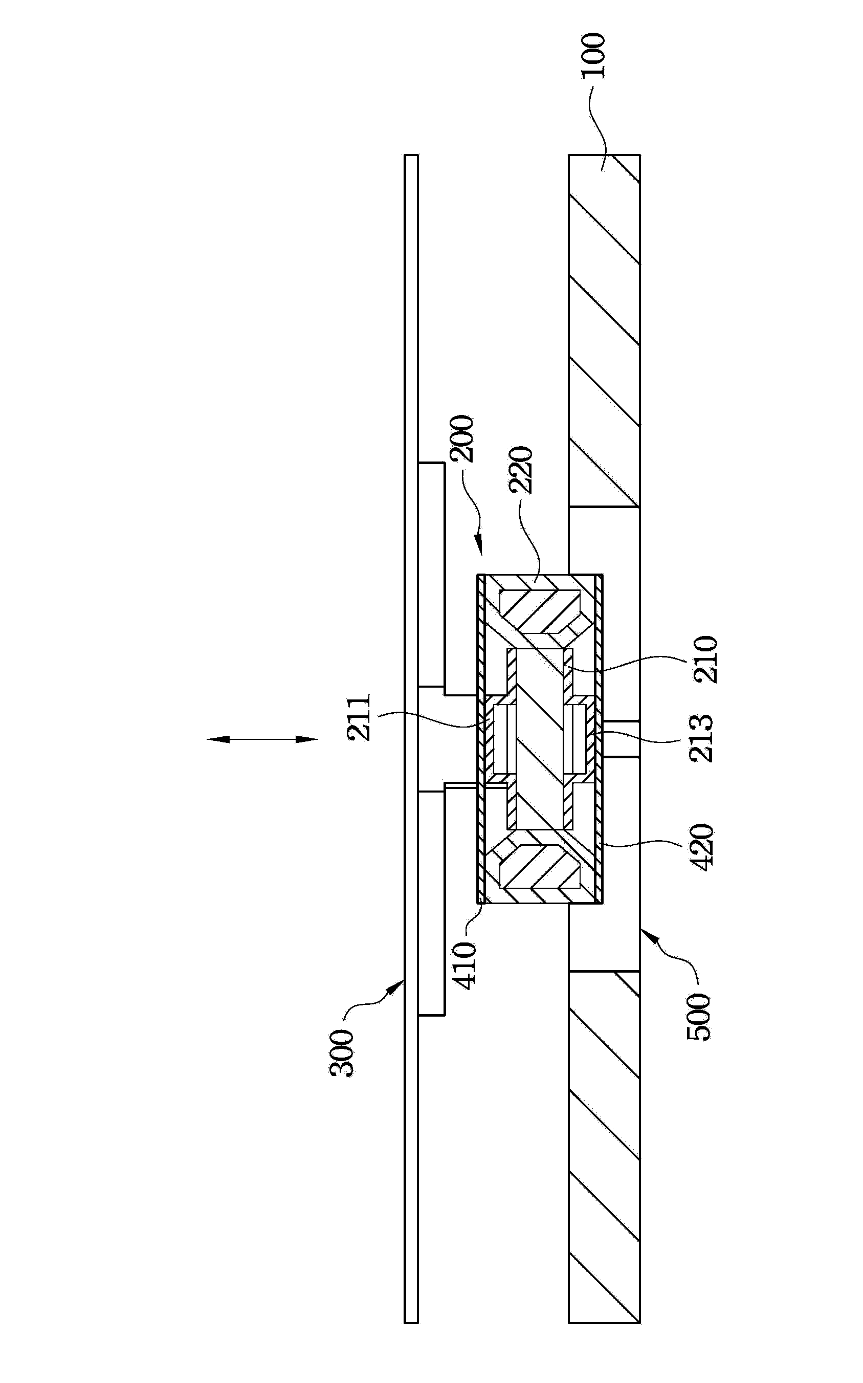
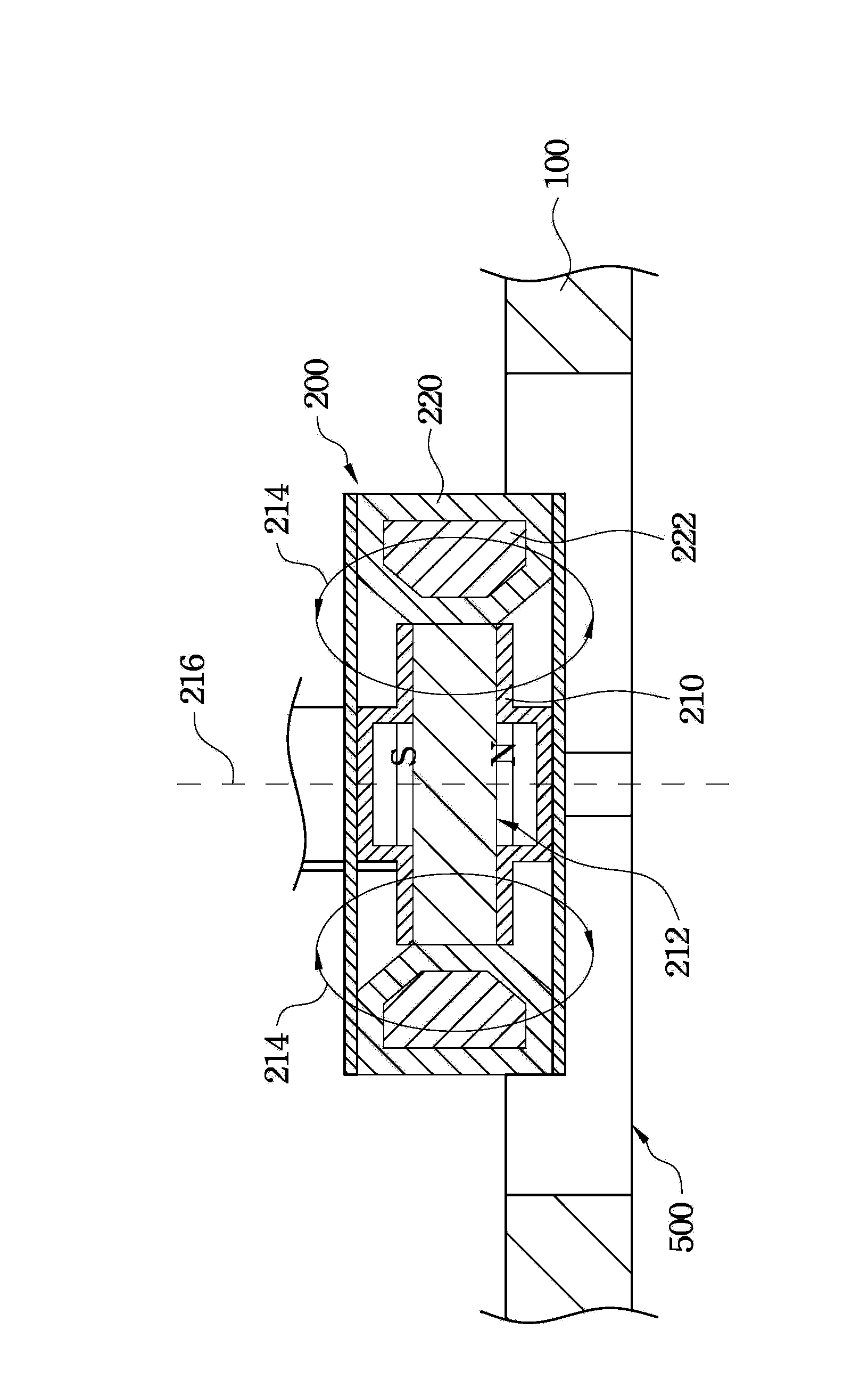
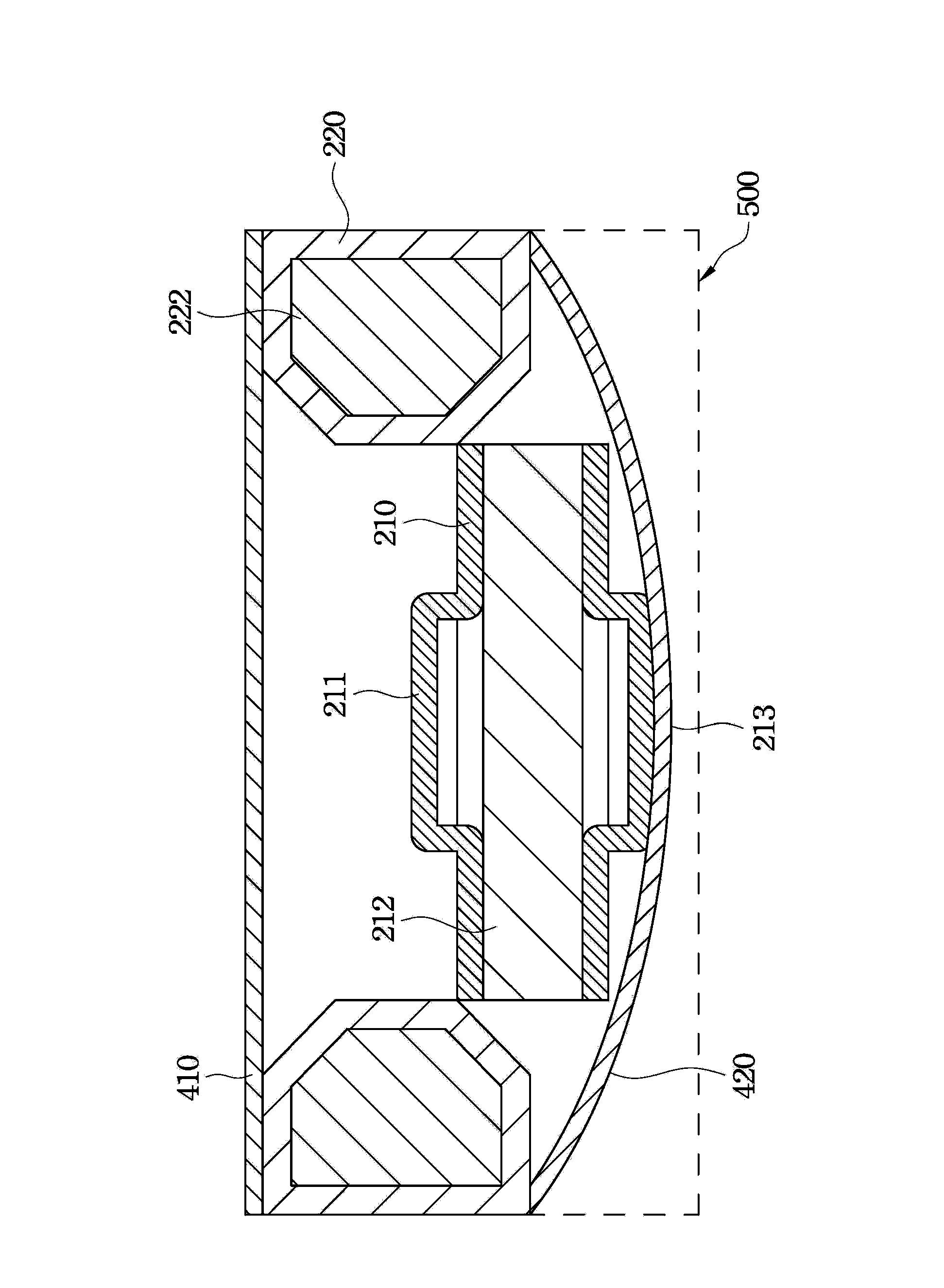
[0062] figure 1 Shown is a cross-sectional view of a vibrating fan according to an embodiment of the present invention. As shown in the figure, the vibration fan includes a base 100 , an electromagnetic actuator 200 and a fan blade 300 . The electromagnetic actuator 200 is disposed on the base 100 , and the electromagnetic actuator 200 includes a movable magnetic element 210 and a fixed magnetic eleme...


PUM


Abstract

The invention provides a vibrating fan which comprises a base, an electromagnetic-type actuator and a fan blade. The electromagnetic-type actuator is arranged on the base and comprises a movable magnetic element and a fixed magnetic element, the movable magnetic element can be in reciprocating motion relatively to the fixed magnetic element, and the fan blade is connected to the movable magnetic element. Reciprocating motion of the movable magnetic element is utilized to drive the fan blade to vibrate so as to disturb air flow, so that heat-dissipating effect is achieved.

Description

technical field [0001] The present invention relates to a fan, in particular to a vibrating fan. Background technique [0002] In recent years, in order to facilitate the portability of portable devices, these portable devices are developing towards light, thin, short, and small, and the demand for heat dissipation is also relatively increased. Therefore, the heat dissipation technology of electronic products has become one of the focuses in related industries. [0003] Generally speaking, a portable device uses a centrifugal fan as a cooling fan, which uses the blades of the fan to rotate in the flow channel, pressurizes through the flow channel, and pushes the wind to the air outlet, so that the air can be dissipated by heat convection. Thermal energy dissipates to the external environment. [0004] However, although the rotation of the blades of the centrifugal fan can effectively push the airflow to remove heat energy, it often causes annoying wind field noise. In add...

Claims


Application Information

Patent Timeline
Patent Type & Authority Applications(China)
IPC IPC(8): F04D25/08F04D29/32
Inventor 陈世轴
Owner DELTA ELECTRONICS INC
Why Eureka
Try Eureka