
Aerodynamic bearing with radially distributed and overlapped elastic foil

An elastic foil and air bearing technology, which is applied in sliding contact bearings, rotating bearings, bearings, etc., can solve the problems of insufficient bearing capacity, low supporting rigidity, and limited overlapping elastic foils, so as to improve the bearing capacity. , Improve the ability to moderate vibration and shock, solve the effect of insufficient stiffness and damping

Active Publication Date: 2013-12-04
HUNAN UNIV
View PDF5 Cites 14 Cited by
  • Summary
  • Abstract
  • Description
  • Claims
  • Application Information

AI Technical Summary

Problems solved by technology

On the one hand, since the support stiffness is completely provided by the single-layer elastic foil, the support stiffness of this type of air bearing is small and the load capacity is insufficient
On the other hand, the overlapping area of ​​adjacent elastic foils has a small contact area during operation, and the damping of the bearing is insufficient, which cannot well alleviate the vibration shock
The lower support stiffness and damping greatly limit the further improvement of the performance of the lapped elastic foil air bearing

Method used


Image

  • Aerodynamic bearing with radially distributed and overlapped elastic foil
  • Aerodynamic bearing with radially distributed and overlapped elastic foil
  • Aerodynamic bearing with radially distributed and overlapped elastic foil

Examples


Embodiment Construction

[0016] The present invention will be further described in detail below in conjunction with the accompanying drawings and specific embodiments.

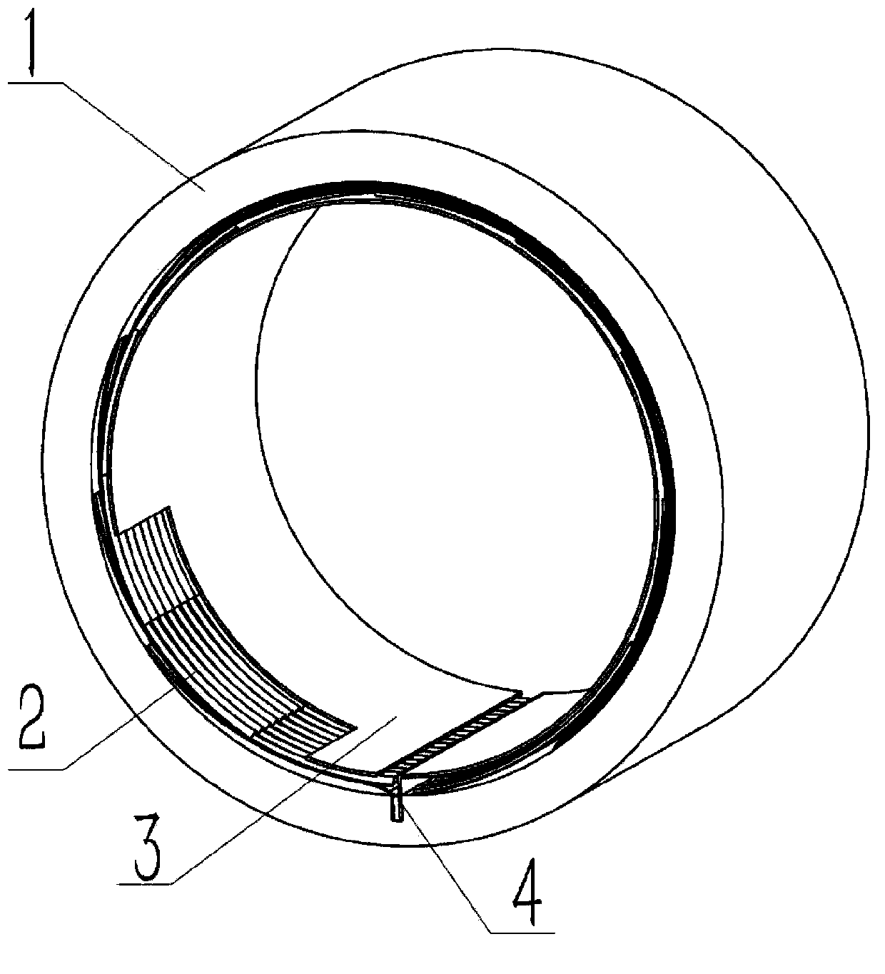
[0017] figure 1 It is a schematic diagram of the overall structure of the radial elastic foil air dynamic pressure bearing. The radial elastic foil air bearing consists of bearing housing 1, elastic foil 2, top foil 3 and end support foil 4.

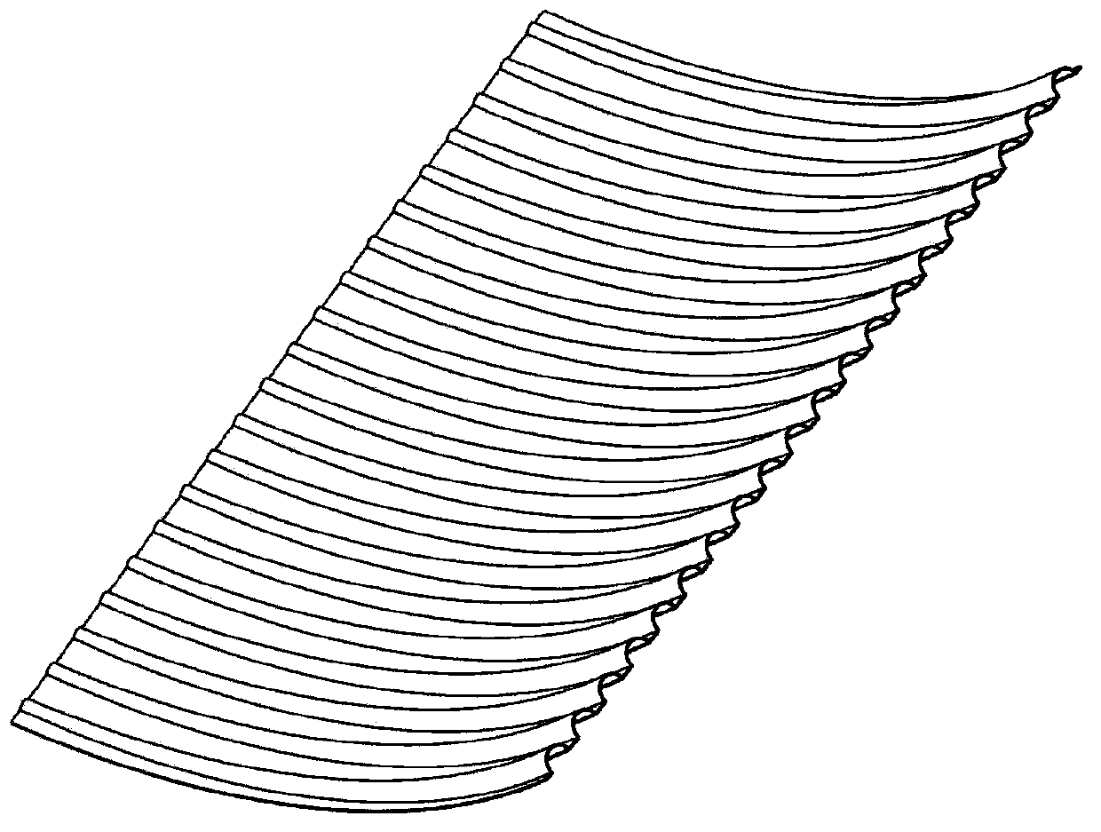
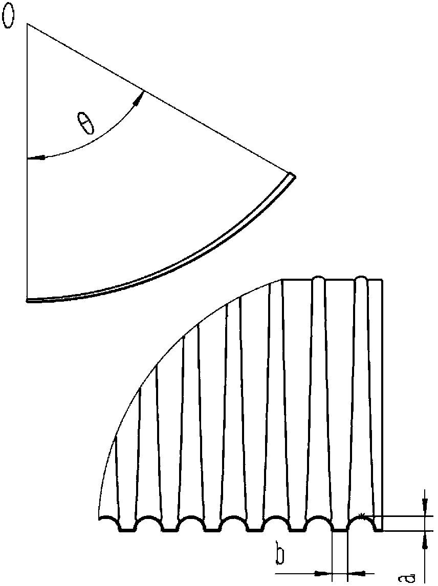
[0018] Wherein the structure of the elastic foil 2 is as figure 2 as shown, image 3 It is a schematic diagram of its main shape parameters. It is made of metal foil pressed by a hydraulic press. After pressing, it forms a wavy protrusion extending along the circumferential direction of the bearing. The angle of the foil arc is θ, and the center of the foil arc is inside the bearing. , the height of the wavy protrusions is a, and the distance between the protrusions is b. In the circumferential direction of the bearing, the number of elastic foils 2 is determined by optimal design, generall...


PUM


Abstract

The invention relates to an aerodynamic bearing with radial elastic foil, in particular to an aerodynamic bearing provided with radially distributed bump foil and a beam-like structure. The novel aerodynamic bearing with the foil comprises a bearing sleeve, the elastic foil and top layer foil, wherein the elastic foil take the shape of tiles; each foil comprises wavy protrusions in the radial direction of the bearing; the widths and the heights of the protrusions become larger and larger gradually; the elastic foil is uniformly arranged in the circumferential direction of the inner surface of the bearing sleeve; one end of the elastic foil is fixed; the other end of the elastic foil is free, lifted by a certain height and overlapped on the upper surface of the adjacent next foil; the wavy protrusions on adjacent foil are in embedded connection with one another; the bottom planes of grooves of the foil are contacted with one another. Therefore, the bearing has high rigidity and high damping property. During design, the rigidity and the damping property of the bearing can be changed conveniently by changing the shape variation regularity of the protrusions on the foil, so as to improve the load-bearing capacity and the impulsive vibration reducing capability of the bearing.

Description

technical field [0001] The invention relates to a radial elastic foil air bearing, more specifically, it relates to an overlapping elastic foil air dynamic pressure bearing with a beam-like structure and radially distributed corrugated foils. Background technique [0002] The foil air bearing is a self-acting elastically supported gas dynamic pressure bearing. It is composed of bearing sleeve, elastic support foil and top foil etc. Compared with ordinary rotor bearings, it has a series of advantages such as high speed, good precision, high reliability, no oil lubrication, small friction loss, and can work in high temperature environment. Foil gas bearings have broad application prospects in aerospace, national defense and military industries, including new-generation fighter jets, high-temperature gas turbines, cruise missiles, and ultra-low temperature cooling systems. At the same time, elastic foil bearing technology is also one of the core technologies of micro gas turb...

Claims


Application Information

Patent Timeline
Patent Type & Authority Applications(China)
IPC IPC(8): F16C27/02
CPCF16C17/024F16C43/02
Inventor 冯凯郭志阳赵雪源
Owner HUNAN UNIV
Learn More