Buffer

A buffer and impact force technology, applied in the direction of shock absorbers, shock absorbers, springs/shock absorbers, etc., can solve the problems of unstable buffering process of heavy equipment, large axial installation volume, buffer rebound bumps, etc. To achieve the effect of highlighting the substantive features, solving the large axial volume and increasing the buffer force

Inactive Publication Date: 2013-12-04
JIGANG GRP
View PDF6 Cites 4 Cited by
  • Summary
  • Abstract
  • Description
  • Claims
  • Application Information

AI Technical Summary

Problems solved by technology

[0003] However, the buffers used in the prior art use ordinary cylindrical springs, which have the defects of large axial installation volume and large rebound after buffering. On the one hand, it takes up a large installation space, and on the other hand, it will cause heavy equipment buffer Instability, resulting in buffer rebound bumps, causing equipment safety accidents
And the technical scheme that solves the above-mentioned technical problem does not appear yet at present, this is the weak point of prior art

Method used


Image

  • Buffer
  • Buffer
  • Buffer

Examples


Embodiment approach 1

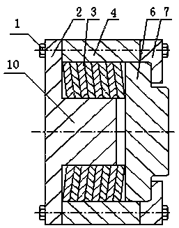
[0027] Depend on figure 1 As shown, a buffer of the present invention includes a base 2 for fixing the buffer and a block 6 for bearing impact force; the middle part of the base 2 has a mandrel 10, and the base 2 has a mandrel An elastic element is provided between one side of 10 and the stopper 6, and an elastic element support sleeve 4 is arranged on the periphery of the elastic element, and an elastic element support sleeve 4 is provided at the connection between the elastic element support sleeve 4 and the stop block 6 for limiting the stopper. The end cover 7 of the block 6, the end cover 7 and the elastic element support sleeve 4 are fixed on the base 2 by bolts 1 .

[0028] Wherein, in the above embodiments, the elastic element is fixedly connected with the stopper 6 .

[0029] Wherein, in the above-mentioned embodiment, the elastic element is a Belleville spring set 3, the free height of the Belleville spring set 3 is greater than the height of the mandrel 10, and one...

Embodiment approach 2

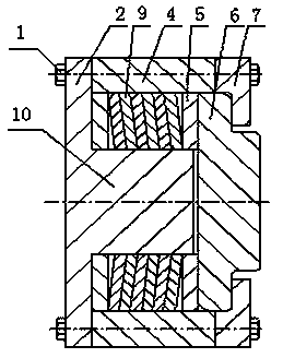
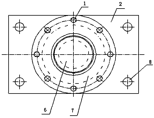
[0034] Depend on figure 2 and image 3 As shown, the difference from Embodiment 1 is that the elastic element in this embodiment includes a Belleville spring set 9 and backing plates 5 fixed at both ends of the Belleville spring set 9, the Belleville spring set 9 and two backing plates The sum of the free heights of 5 is greater than the height of the mandrel 10 , and the backing plate 5 at one end of the Belleville spring group 9 adjacent to the stop 6 is fixed on the stop 6 . The butterfly spring group 9 is fixed on the stopper 6 through the backing plate 5, and forms a stressed living body with the stopper 6, which improves the stability of the buffering process of the buffer, thereby increasing the service life of the buffer.

[0035] In summary, when the present invention is used, the buffer is fixed to the corresponding position of the equipment body through the four bolt holes 8 on the base 2. When the equipment body is impacted, the stopper 6 directly bears all the i...


PUM


Abstract

The invention provides a buffer, which comprises a base used for fixing the buffer and a check block used for bearing impact force, wherein a mandrel is arranged on the middle part of the base; an elastic element is arranged between one side, which is provided with the mandrel, of the base and the check block; an elastic element support sleeve is arranged on the periphery of the elastic element; an end cover used for limiting the check block is arranged at the joint of the elastic element support sleeve and the check block; the end cover and the elastic element support sleeve are fixed on the base through bolts. According to the buffer, the defect of large axial size of the conventional buffer is overcome, the phenomena of large-amplitude rebounding and jumping in a buffering process are avoided while huge impact force can be borne, and high buffering stability and high practicability are realized.

Description

technical field [0001] The invention relates to the field of mechanical manufacturing, in particular to a buffer. Background technique [0002] In mining machinery, cement crushing equipment, such as vertical mills, has a huge volume and weight. This type of equipment will generate a huge impact force during the work process. In order to absorb the impact force of the equipment during the work process, protect the equipment, and extend the The service life often requires the use of buffers. [0003] However, the buffers used in the prior art use ordinary cylindrical springs, which have the defects of large axial installation volume and large rebound after buffering. On the one hand, it takes up a large installation space, and on the other hand, it will cause heavy equipment buffer Instability, resulting in buffer rebound bumps, causing equipment safety accidents. And there is no technical solution for solving the above-mentioned technical problems at present, which is the ...

Claims


Application Information

Patent Timeline
IPC IPC(8): F16F7/104F16F7/116
Inventor 管延科张文周黄一声
Owner JIGANG GRP
Why Eureka
Try Eureka