Two-segment enveloping worm end face meshing worm transmission device

A technology of worm drive and enveloping ring, applied in the direction of transmission device, transmission device parts, gear transmission device, etc., can solve the problems of insufficient load-carrying capacity worm throat stiffness, automatic elimination, and many meshing teeth, etc. The effect of popularization, large bearing capacity and large number of meshing teeth

Inactive Publication Date: 2013-12-04
XIHUA UNIV
View PDF8 Cites 9 Cited by
  • Summary
  • Abstract
  • Description
  • Claims
  • Application Information

AI Technical Summary

Problems solved by technology

[0005] The purpose of the present invention is to overcome the deficiencies of the prior art and provide a two-stage enveloping torus end face meshing worm transmission device. By adopting the special form of worm end face meshing, the number of meshing teeth between the worm and the worm gear is large and the load capacity is large. Solved the problem of insufficient rigidity of the throat of the ordinary enveloping toroidal worm and the automatic elimination of the backlash after tooth surface wear

Method used


Image

  • Two-segment enveloping worm end face meshing worm transmission device
  • Two-segment enveloping worm end face meshing worm transmission device
  • Two-segment enveloping worm end face meshing worm transmission device

Examples


Embodiment 1

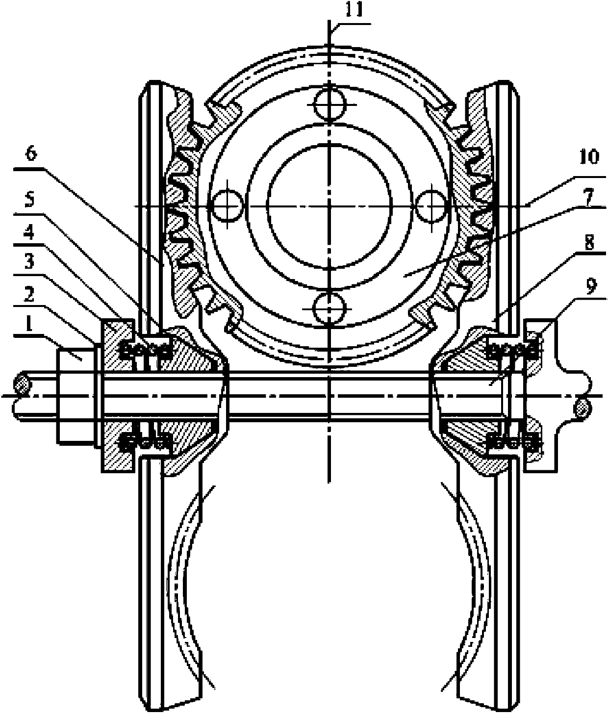
[0030] In this embodiment, the structure of the two-stage enveloping toroidal end meshing worm gear is as follows: figure 1 As shown, it includes a worm wheel 7, a left section worm 6, a right section worm 8, a connecting shaft 9 and two sets of axial positioners for adjusting the meshing backlash of the worm and worm gear. The connecting shaft 9 is a spline shaft, such as Figure 4 , Figure 5 shown. The left section worm 6 and the right section worm 8 are taken from the end face of the plane enveloping toroidal worm and have the same shape and structure. The position where their tooth surfaces mesh with the tooth surfaces on both sides of the worm wheel is that the worm wheel is parallel to the centerline 10 of the connecting shaft. The upper part and the lower part, their inner holes are keyway structures that match the spline shaft. The two sets of axial positioners are composed of spring seat 3, adjustment spring 4 and positioning head 5, wherein the spring seat 3 and ...

Embodiment 2

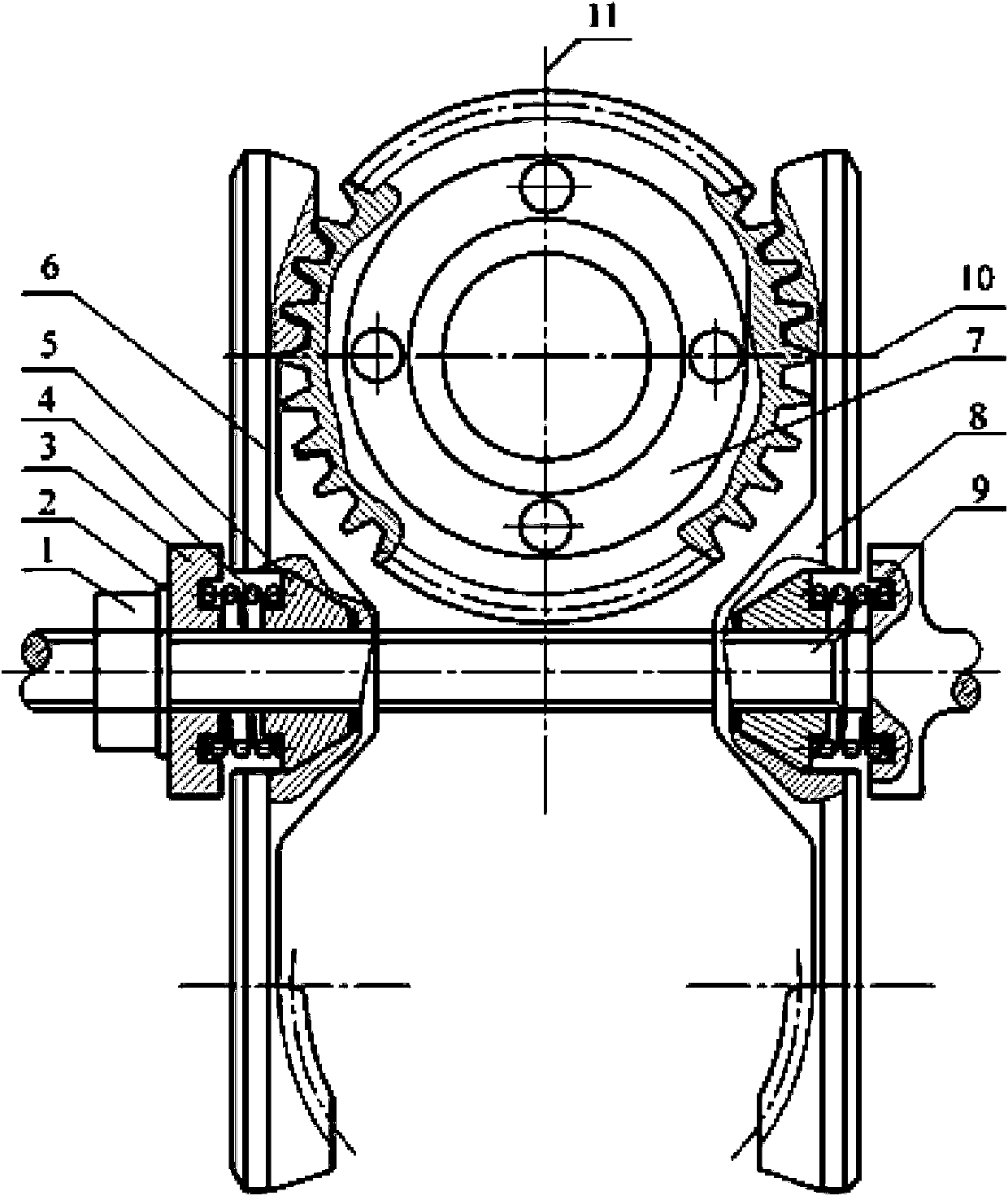
[0033]In this embodiment, the structure of the two-stage enveloping toroidal end meshing worm gear is as follows: figure 2 As shown, it includes a worm wheel 7, a left section worm 6, a right section worm 8, a connecting shaft 9 and two sets of axial positioners for adjusting the meshing backlash of the worm and worm gear. The difference from Embodiment 1 is that the tooth surfaces on both sides of the worm wheel are located above the center line 10 of the worm wheel parallel to the connecting shaft, respectively meshing with the tooth surfaces of the left section worm 6 and the right section worm 8, and the left section worm 6 and the right section worm The structure of section worm screw 8 matches it.

Embodiment 3

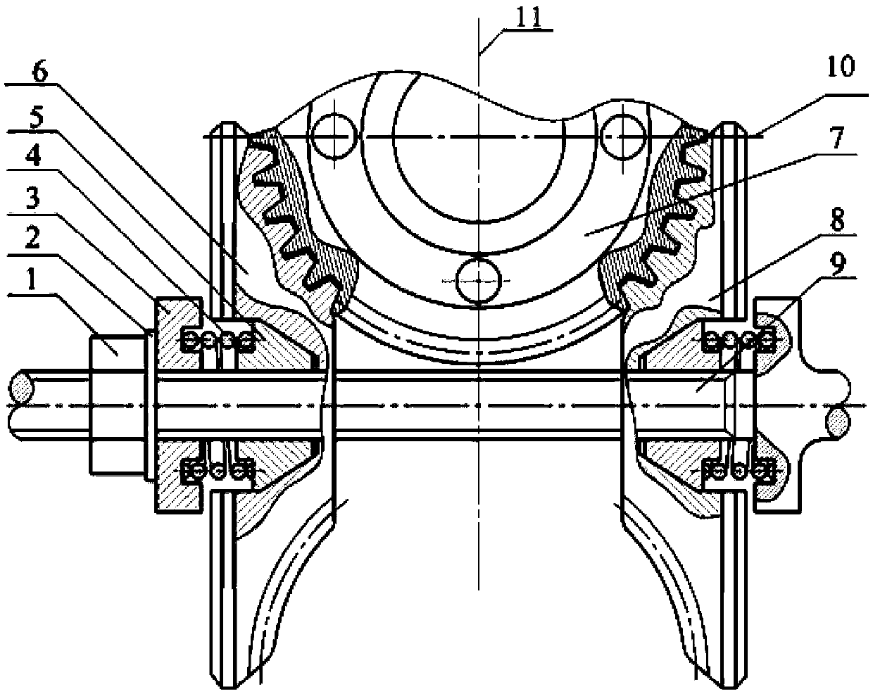
[0035] In this embodiment, the structure of the two-stage enveloping toroidal end meshing worm gear is as follows: figure 2 As shown, it includes a worm wheel 7, a left section worm 6, a right section worm 8, a connecting shaft 9 and two sets of axial positioners for adjusting the meshing backlash of the worm and worm gear. The difference from Embodiment 1 is that the tooth surfaces on both sides of the worm wheel are located below the centerline 10 of the worm wheel parallel to the connecting shaft, respectively meshing with the tooth surfaces of the left section worm 6 and the right section worm 8, and the left section worm 6 and the right section worm The structure of section worm screw 8 matches it.


PUM


Abstract

A two-segment enveloping worm end face meshing worm transmission device comprises a worm gear, a left segment worm, a right segment worm, a connecting shaft and axial positioning devices used for adjusting a worm and worm gear meshing side gap. The left segment worm and the right segment worm are taken from the end face of an enveloping worm and are identical in shape and structure. The left segment worm and the right segment worm are vertical to the center line of the connecting shaft relative to the worm gear and are axisymmetrically arranged on the connecting shaft, and a gap is reserved between the left segment worm and the right segment worm for installation of the worm gear. The worm gear is located between the left segment worm and the right segment worm and is arranged on a worm gear shaft, and different portions of the tooth faces on the two sides of the worm gear are meshed with the tooth faces of the left segment worm and the tooth faces of the right segment worm respectively. The axial positioning devices are two in number, and are respectively combined with the left segment worm and the right segment worm and installed on the connecting shaft. On the conditions that the number of meshed teeth of the worms and the worm gear is large and bearing capacity is large, the worm transmission device of the structure effectively solves the difficulty that rigidity of the throat portion of a common enveloping worm is not enough, and solves the problem that a backlash is automatically eliminated after the tooth faces are abraded.

Description

technical field [0001] The invention belongs to the field of high-precision worm gear transmission, in particular to a backlash-free worm transmission device. Background technique [0002] Due to the backlash of the teeth in the traditional precision gear transmission, there are often delays and lags between the output and the input, and at the same time cause meshing impacts and self-excited vibrations. The transmission accuracy and position accuracy of the entire system will be reduced accordingly, and even lead to The entire system cannot be used normally. Eliminating the impact of backlash on transmission accuracy and pursuing high transmission efficiency and load capacity are the main goals and development trends of the exploration and research of new precision gear transmission methods. For example: in the laser confinement nuclear fusion project, it is necessary to realize the ultra-precise pose adjustment of 5 degrees of freedom for the grating, the linear and rotat...

Claims


Application Information

Patent Timeline
Patent Type & Authority Applications(China)
IPC IPC(8): F16H1/22F16H55/24F16H57/023
Inventor 王进戈邓星桥郑有春
Owner XIHUA UNIV
Why Eureka
Try Eureka