wifi antenna testing system and method
A technology for testing systems and antennas, applied in antenna radiation patterns, measuring devices, measuring electrical variables, etc., can solve problems such as low efficiency, inability to directly save test data and analysis results, and achieve the effect of speeding up
- Summary
- Abstract
- Description
- Claims
- Application Information
AI Technical Summary
Problems solved by technology
Method used
Image

Examples
Embodiment 1
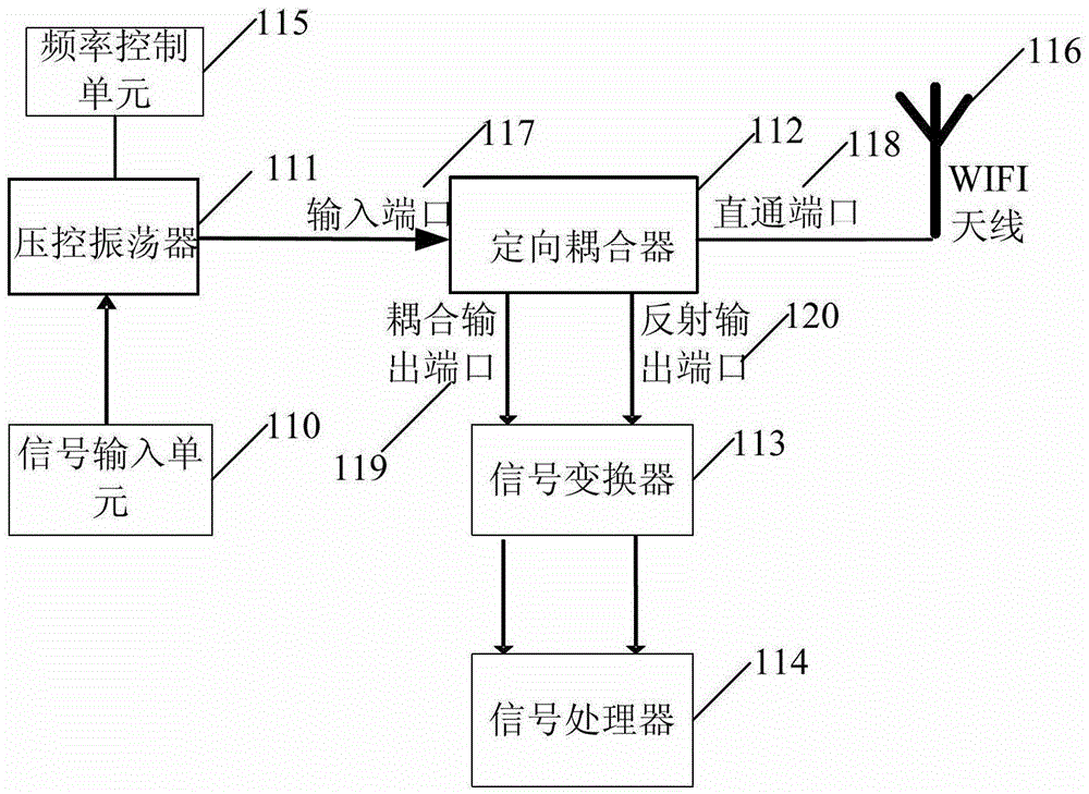
[0027] figure 1 A schematic structural diagram of a WIFI antenna test system provided in Embodiment 1 of the present invention, the system is suitable for measuring the radio frequency passive performance of the WIFI antenna, that is, the return loss, such as figure 1 As shown, the test system of the present invention includes a signal input unit 110 , a voltage controlled oscillator 111 , a directional coupler 112 , a signal converter 113 and a signal processor 114 . Wherein: signal input unit 110 is used for inputting test signal; Voltage-controlled oscillator 111 is connected with described signal input unit 110, is used for generating the radio frequency signal of setting frequency according to described test signal; Directional coupler 112 comprises input port 117, Straight-through port 118, coupled output port 119 and reflection output port 120, wherein the input port 117 is connected to the voltage-controlled oscillator to receive the radio frequency signal; the straigh...
Embodiment 2
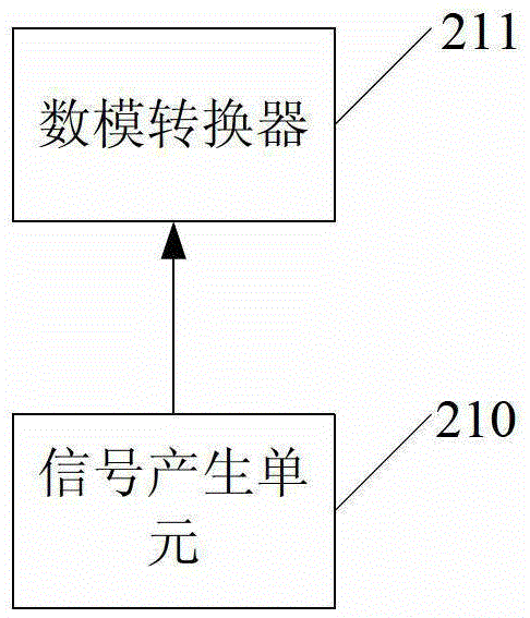
[0034] figure 2 A schematic structural diagram of the signal input unit in the WIFI antenna test system provided by Embodiment 2 of the present invention, such as figure 2 As shown, this embodiment is based on the above embodiments, wherein the signal input unit preferably includes a signal generating unit 210 and a digital-to-analog converter 211, wherein:
[0035] A signal generating unit 210, configured to generate a test signal in the form of a digital signal;
[0036] The digital-to-analog converter 211 is connected to the signal generating unit 210 and is used for converting the test signal in the form of a digital signal into a test signal in the form of an analog signal.
[0037] In this embodiment, the signal generation unit 210 is equipped with control software, which can control the change of the voltage.
Embodiment 3
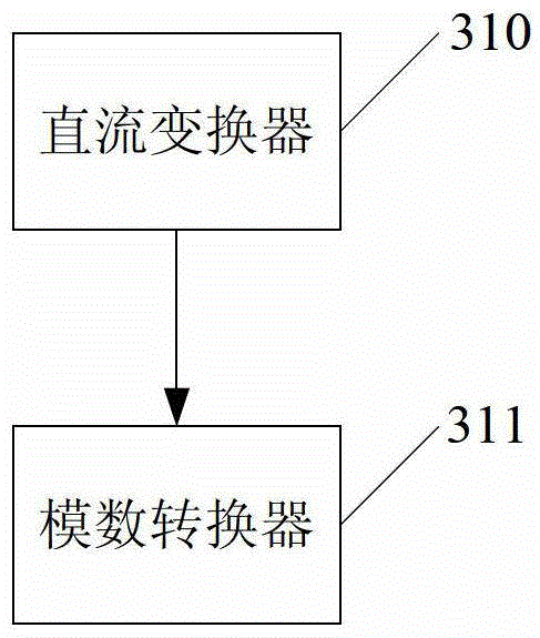
[0039] image 3 A schematic structural diagram of the signal converter in the WIFI antenna test system provided by Embodiment 3 of the present invention, such as image 3 As shown, this embodiment is based on the above embodiments, wherein the signal converter preferably includes a DC converter 310 and an analog-to-digital converter 311, wherein:
[0040] A DC converter 310, connected to the coupling output port and the reflection output port of the directional coupler, respectively, for converting the first signal and the second signal in the form of radio frequency into a first DC signal and a second DC signal respectively ;
[0041] The analog-to-digital converter 311 is connected to the DC converter and used to convert the first DC signal and the second DC signal into a first digital signal and a second digital signal respectively.
[0042] In the embodiment of the present invention, the output of the directional coupler is a radio frequency signal, which cannot be direc...
PUM
 Abstract
Description
Claims
Application Information
 - R&D
- Intellectual Property
- Life Sciences
- Materials
- Tech Scout
- Unparalleled Data Quality
- Higher Quality Content
- 60% Fewer Hallucinations
Browse by: Latest US Patents, China's latest patents, Technical Efficacy Thesaurus, Application Domain, Technology Topic, Popular Technical Reports.
© 2025 PatSnap. All rights reserved.Legal|Privacy policy|Modern Slavery Act Transparency Statement|Sitemap|About US| Contact US: help@patsnap.com