Test system which

A technology for testing systems and chips to be tested, which is applied in the direction of electronic circuit testing, measuring electricity, measuring devices, etc., can solve the problems of long time-consuming, etc., and achieve the effect of improving the testing speed and prolonging the service life

Pending Publication Date: 2018-10-09
SHENZHEN RAYBOW OPTOELECTRONICS
View PDF9 Cites 26 Cited by
  • Summary
  • Abstract
  • Description
  • Claims
  • Application Information

AI Technical Summary

Problems solved by technology

[0004] The existing COS test system is composed of discrete instruments, and there is only one test station, which mainly has the following problems: this method is purely manual operation by the operator, because there is only one test station, and COS material loading needs to be completed sequentially , test operation, maintain data, COS blanking, time-consuming

Method used


Image

  • Test system which
  • Test system which
  • Test system which

Examples


Embodiment Construction

[0026] The following will clearly and completely describe the technical solutions in the embodiments of the present application. Obviously, the described embodiments are only some of the embodiments of the present application, rather than all the embodiments. Based on the embodiments in this application, all other embodiments obtained by persons of ordinary skill in the art without making creative efforts belong to the scope of protection of this application.

[0027] It is worth noting that the directional terms mentioned in this application, for example, "upper", "lower", "front", "rear", "left", "right", "inner", "outer", " "side", etc., are only referring to the directions of the attached drawings. Therefore, the direction terms used are for better and clearer description and understanding of the present application, rather than indicating or implying that the referred device or element must have a specific orientation. , are constructed and operate in a particular orienta...


PUM


Abstract

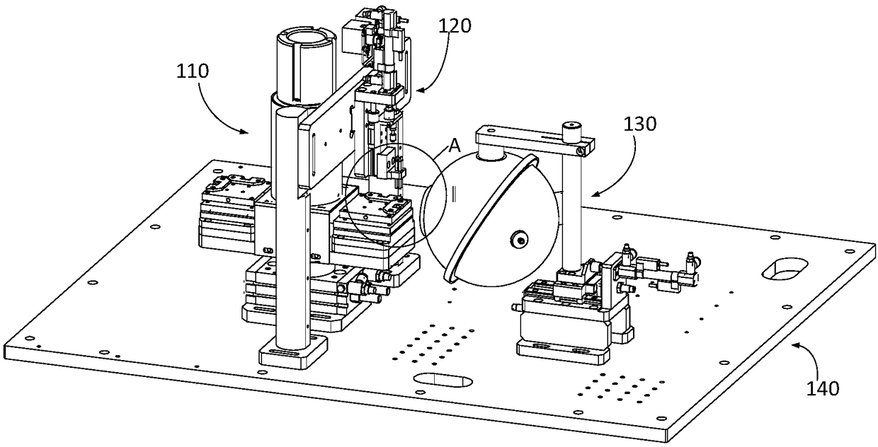
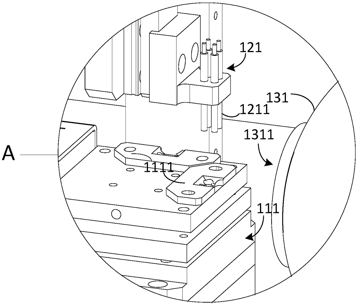
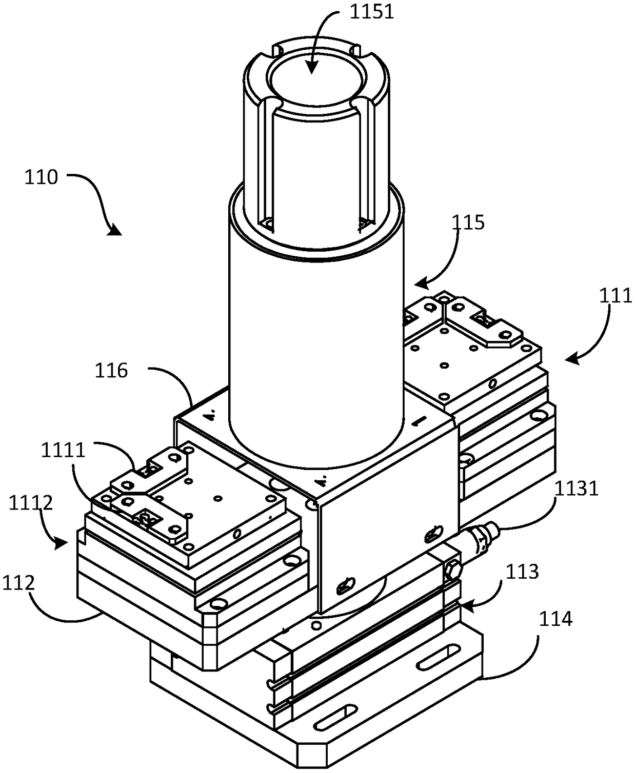
The invention relates to a test system which is used for testing a semiconductor laser chip. The test system comprises a loading and unloading device, a probe assembly and an integrating sphere assembly; wherein the loading and unloading device comprises a plurality of stations for placing a to-be-tested chip; the probe assembly comprises a plurality of probes arranged above the to-be-tested chip;and the integrating sphere assembly comprises an integrating sphere with an opening which is close to the to-be-tested chip. When the current flows through the pin of the to-be-tested chip through the probes, the opening receives an optical signal sent by the to-be-tested chip. The probe assembly and the integrating sphere assembly are respectively arranged to be capable of moving in the verticaldirection and the horizontal direction, so that the detection element is protected, and the service life is prolonged. The test speed is further improved through orderly movement.

Description

technical field [0001] The present application relates to the field of chip testing, in particular to a testing system for semiconductor laser chips. Background technique [0002] The most common packaging form of semiconductor laser chips is COS (Chip On Submount), which is directly packaged on a heat sink with high thermal conductivity. The process at this stage is related to the quality of the semiconductor laser, so after this packaging process step, it needs to pass strict functional testing, and the quality of its performance parameters directly affects the quality of the semiconductor laser. [0003] Testing and characterizing the performance parameters of semiconductor laser chips (such as LIV (Light-Current-Voltage, light intensity-current-voltage) characteristics, spectral characteristics, FFP (Far-Field Pattern, far-field pattern) characteristics) is the key to a deep understanding of lasers. The key to chip characteristics, optimized chip structure design and pe...

Claims


Application Information

Patent Timeline
Patent Type & Authority Applications(China)
IPC IPC(8): G01R31/28
CPCG01R31/2851
Inventor 胡海刘文斌王泰山李成鹏李国泉
Owner SHENZHEN RAYBOW OPTOELECTRONICS
Why Eureka
Try Eureka