Double-channel optical performance testing device of integrated waveguide modulator and polarization crosstalk identification and processing method thereof
A technology of integrated waveguide and polarization crosstalk, which is applied in the field of dual-channel optical performance testing devices, can solve the problems that do not involve the optical performance of the output channel of the Y waveguide device and its difference test and evaluation, and achieve high test efficiency and good stability , the effect of small environmental impact
- Summary
- Abstract
- Description
- Claims
- Application Information
AI Technical Summary
Problems solved by technology
Method used
Image
Examples
Embodiment 1
[0144]Embodiment 1——Waveguide measurement device based on Mach-Zehnder demodulation interferometer
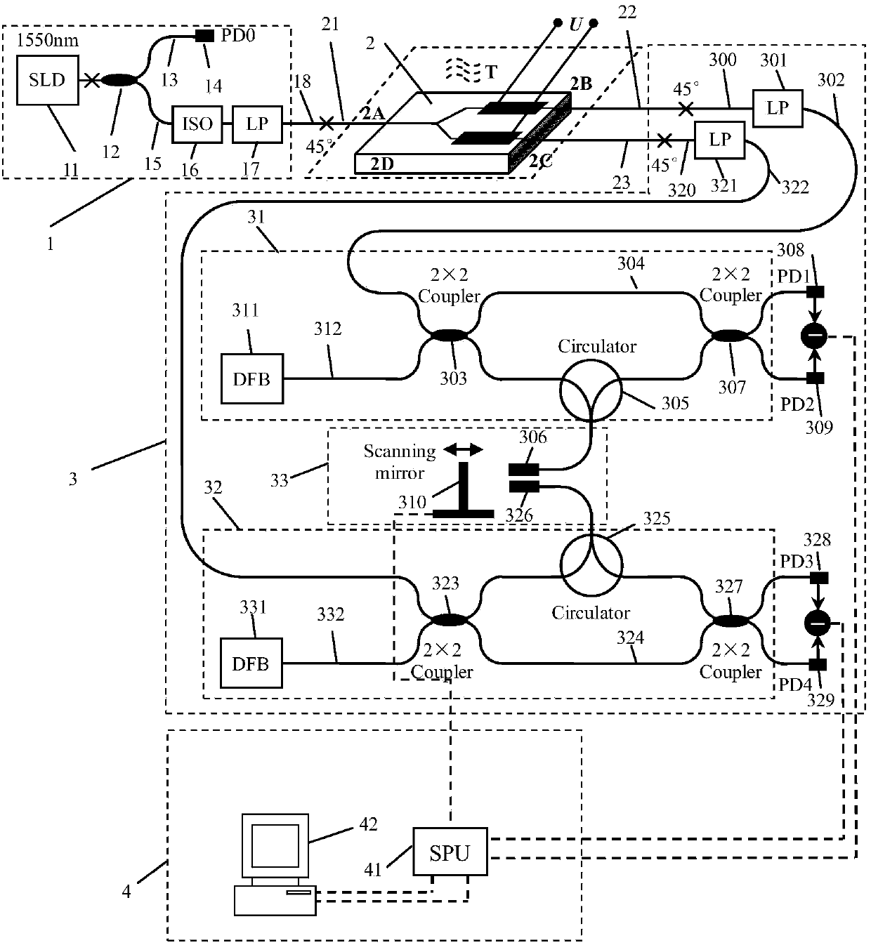
[0145] Device measurement devices such as image 3 As shown, the device selection and parameters of the white light interferometry device are as follows:
[0146] (1) The central wavelength of the broadband light source 11 is 1550nm, the half-spectrum width is greater than 45nm, the output power of the fiber is greater than 2mW, the spectral ripple of the light source is <0.05dB (the peak amplitude is about -60dB), and the optical path range of the coherence peak is 4-7mm; DFB The half-spectrum width of the light source 311 is less than 50MHz, and the output power of the fiber is greater than 1mW;
[0147] (2) 2 / 98 fiber coupler 12 working wavelength 1550nm, splitting ratio 2:98;
[0148] (3) Optical fiber isolator 16 has a working wavelength of 1550nm, insertion loss of 0.8dB, and isolation >35dB;
[0149] (4) The optical fiber polarizer 17, the working wavelength of the fi...
Embodiment 2
[0159] Embodiment 2——Double-channel simultaneous measurement of the Y-waveguide device with the slow axis of the pigtail and the fast axis of the waveguide chip
[0160] The measurement device diagram of the Y waveguide device is shown in the figure image 3 As shown, the optical performance measurement process is as follows Figure 4 shown.
[0161] (1) From step 701, it can be seen that the length l of the Y waveguide input pigtail is measured W-i is 1.53 meters;
[0162] (2) It can be known from step 702 that the input pigtail l W-i The theoretical optical path length (Δn f Press 5×10 -4 Count) S W-i =0.765mm; while S ripple =4~7mm, it can be seen that the input extension fiber must be welded;
[0163] (3) According to step 703, it can be known that connecting the extension fiber l f-i must be at least 7×10 in length -3 / 5×10 -4 =14 meters, the actual selection is 15 meters;
[0164] (4) According to step 704, it can be seen that the length of the measured waveg...
Embodiment 3
[0173] Embodiment 3——Measurement of the change of two output channels of Y waveguide device with temperature
[0174] The measurement device of the Y waveguide device is still as image 3 As shown, the difference from Example 2 is that the other Y-waveguide 2 to be tested connected to the broadband light source 1 and the optical path demodulation device 3 is placed in a temperature control box and changed from -50°C to 80°C Change the temperature, as in Figure 4 In the measurement process and data analysis method shown, various optical variations of the Y waveguide device with temperature are obtained from the first measurement channel and the second measurement channel at the same time.
[0175] The test results show that the crosstalk at the coupling point of the input / output pigtail and the waveguide chip is very sensitive to temperature, such as Figure 8-10 As shown, the power coupling crosstalk between the Y waveguide input pigtail, the first output channel pigtail, t...
PUM
| Property | Measurement | Unit |
|---|---|---|
| Length | aaaaa | aaaaa |
Abstract
Description
Claims
Application Information
 - R&D
- Intellectual Property
- Life Sciences
- Materials
- Tech Scout
- Unparalleled Data Quality
- Higher Quality Content
- 60% Fewer Hallucinations
Browse by: Latest US Patents, China's latest patents, Technical Efficacy Thesaurus, Application Domain, Technology Topic, Popular Technical Reports.
© 2025 PatSnap. All rights reserved.Legal|Privacy policy|Modern Slavery Act Transparency Statement|Sitemap|About US| Contact US: help@patsnap.com


