
A DC electric energy meter verification device

A technology of a DC electric energy meter and a verification device, which is applied in the direction of measuring devices, measuring electrical variables, instruments, etc., can solve the problems of low precision, complicated operation steps, low verification efficiency, etc., and achieves the effects of high precision, convenient operation and friendly interface

Active Publication Date: 2015-10-28
ELECTRIC POWER RES INST OF GUANGXI POWER GRID CO LTD +1
View PDF12 Cites 0 Cited by
  • Summary
  • Abstract
  • Description
  • Claims
  • Application Information

AI Technical Summary

Problems solved by technology

This scheme consumes a lot of power during verification
[0006] 3. The resistance method or Hall method is used for large current measurement. The accuracy of this kind of scheme is relatively low, which are 0.2% per year and 0.5% per year respectively.
However, the traditional DC comparator can only be used for slow measurement and comparison, and cannot be used to capture rapid changes in current, so it cannot be used as a feedback component of a large current generator, which severely limits the development of high-precision current sources.
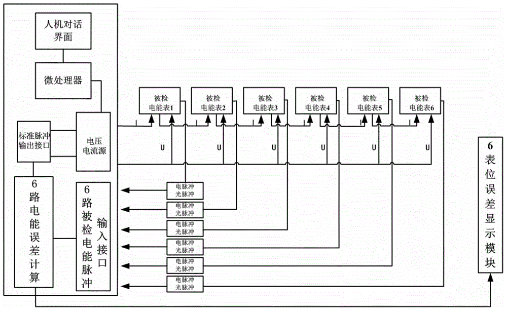
[0007] In addition, the existing devices of this type are basically only aimed at the detection of a single table, and there are no relevant technical literature reports on the detection device of multi-epitopes.
Most of the existing devices of this type require manual recording and a large amount of data processing work, the verification efficiency is low, and human error is prone to occur
Most of the existing devices of this type only have button input mode, no touch screen input, the operation steps are cumbersome, and the interface is not friendly

Method used


Image

  • A DC electric energy meter verification device
  • A DC electric energy meter verification device
  • A DC electric energy meter verification device

Examples


Embodiment Construction

[0041] The technical solution of the present invention will be further described below through examples.

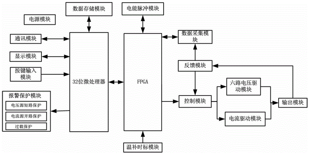
[0042] Such as figure 1As shown, the DC watt-hour meter verification device of the present invention includes a 32-bit microprocessor, FPGA, power supply module, communication module, display module, key input module, alarm protection module, data storage module, electric energy pulse module, temperature compensation Time scale module, data acquisition module, control module, six-way voltage drive module, current drive module, output module and feedback module, the 32-bit microprocessor of the device communicates with FPGA, data storage module, communication module and display module respectively through the control bus , button input module, and alarm protection module; FPGA is connected to 32-bit microprocessor, control module, electric energy pulse module, temperature compensation time scale module, and data acquisition module; the control module is connected to six-wa...


PUM


Abstract

Provided are a detection device and detection method for a direct current electric energy meter. A 32-bit microprocessor of the device is respectively connected with a field programmable gate array (FPGA), a data storage module, a communication module, a display module, a key input module and an alarm protection module; the FPGA is respectively connected with the 32-bit microprocessor, a control module, an electric energy pulse module, a temperature compensation time scale module and a data collecting module; the control module is respectively connected with a six-way voltage driving module, a current driving module and a feedback module; an output module is connected with the six-way voltage driving module, the current driving module and the feedback module; and the feedback module is respectively connected with the output module, the control module and the data collecting module. The short-term stability of the device is superior to 0.005% / min, an alternating current ripple wave is extremely small, the adjusting fineness is as high as 5ppm, and the device is extremely high in reliability and can continuously work for 24h.

Description

technical field [0001] The invention relates to a verification device and a detection method for a DC electric energy meter. Background technique [0002] According to the characteristics of electric vehicle on-board batteries, large and medium-sized electric vehicles generally use DC charging. Since the DC voltage during charging is 400-800V and the current is 0-500A, the existing DC electric energy meter can no longer meet this demand. Therefore, some domestic electric energy meter manufacturers have developed new DC electric energy meters for electric energy measurement of DC charging piles. . Correspondingly, due to the high rated voltage and rated current of this type of DC watt-hour meter, the existing common metering verification device cannot verify it, so it is necessary to develop a DC watt-hour meter verification device with high precision and wide output range. [0003] At present, the schemes adopted by the DC meter verification device on the market mainly inc...

Claims


Application Information

Patent Timeline
Patent Type & Authority Patents(China)
IPC IPC(8): G01R35/04
Inventor 曾博周新华韩帅李刚刘路卿柏元邓文陈俊
Owner ELECTRIC POWER RES INST OF GUANGXI POWER GRID CO LTD
Learn More