
A dual-row power tube electric vehicle controller

A technology of electric vehicle controller and power tube, applied in the direction of sealing shell, cooling/ventilation/heating transformation, etc., can solve the problems of power tube burnout failure, power burnout failure, short circuit inside the shell, etc., to ensure timely Effectiveness and effectiveness, avoid excessive heat concentration, good sealing consistency

Active Publication Date: 2016-11-23
JIANGSU YUNYI ELECTRIC
View PDF5 Cites 0 Cited by
  • Summary
  • Abstract
  • Description
  • Claims
  • Application Information

AI Technical Summary

Problems solved by technology

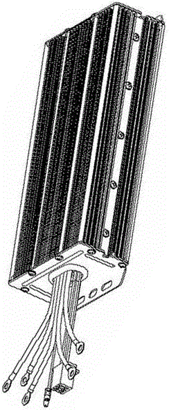
The controller with this structure often has the following problems in actual use: First, the sealing performance of the front and rear cover plates is not good, and the internal circuit is often short-circuited due to rain, water splashing on the road, etc. in the housing.
The second is that the eighteen power tubes are distributed in a single row, and the heat generated by the power tubes is too concentrated during operation. In addition, when the heat is transmitted to the aluminum heat dissipation shell through the heat-conducting aluminum strip, the heat conduction path is too long, and the heat dissipation effect is poor. Timely and effective export will cause the power tube to burn out and fail, and the controller function will be lost
Third, due to the influence of the thread quality on the heat-conducting aluminum strip, the locking force of individual power tubes and heat-conducting aluminum strips is small or slippery when the screws are locked together, resulting in poor fit of individual power tubes, and the heat of the power tubes cannot be effectively conducted. Cause individual power burnout failure, loss of controller function

Method used


Image

  • A dual-row power tube electric vehicle controller
  • A dual-row power tube electric vehicle controller
  • A dual-row power tube electric vehicle controller

Examples


Embodiment Construction

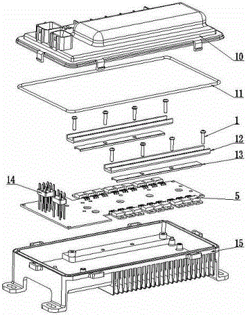
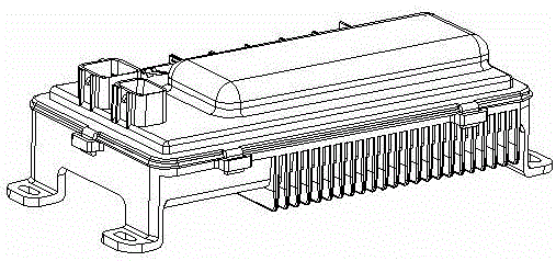
[0012] Such as image 3 , Figure 4 Shown: the present invention comprises plastic cover 10, sealing strip 11, screw 1, pressure plate 12, rubber strip 13, eighteen power tubes 5 welded on the circuit board, two groups of functional plugs 14 welded on the circuit board, Cast aluminum cooling case 15. The controller is a double-row power tube 5 electric vehicle controller with an upper and lower structure. The upper part is a plastic cover 10, and the lower part is a cast aluminum heat dissipation shell 15. There is a sealing strip 11 between the plastic cover 10 and the cast aluminum heat dissipation shell 15, and the inside contains There are eighteen power tubes 5 and two sets of functional plugs 14 welded on the circuit board. The screws 1 pass through the pressure plate 12 and the rubber strip 13 and are assembled on the cast aluminum heat sink 15. There is a place on the upper edge of the cast aluminum heat sink 15 The groove of the sealing strip 11 has strip-shaped hea...


PUM


Abstract

The invention discloses an electromobile controller with two rows of power tubes. The electromobile controller is composed of a plastic cover cap, a sealing strip, screws, pressing plates, rubber strips, eighteen power tubes welded on a circuit board, two sets of functional plugs welded on the circuit board, and an aluminum-cast heat-dissipating shell. The electromobile controller is characterized in that the controller is of an upper-lower structure, the plastic cover cap is arranged on the upper side, the aluminum-cast heat-dissipating shell is arranged on the lower side, the sealing strip is arranged between the plastic cover cap and the aluminum-cast heat-dissipating shell, and the power tubes and the functional plugs both welded on the circuit board are contained inside the controller. The electromobile controller has the advantages that the power tubes welded on the circuit board are compressed by the pressing plates and the rubber strips to be directly and closely fit with the plane of the aluminum-cast heat-dissipating shell for heat dissipation, and a heat conduction path is shortest, so that timeliness and effectiveness of heat conduction are guaranteed; after compressing the sealing strip, the plastic cover cap is in buckling connection with the aluminum-cast heat-dissipating shell, so that sealing performance of the controller is effectively guaranteed.

Description

technical field [0001] The invention relates to a controller for an electric vehicle, in particular to a controller for an electric vehicle with double-row power tubes. Background technique [0002] With the development of society and the continuous increase of fuel vehicles, the shortage of natural resources such as petroleum fuels and the global warming caused by fuel emissions have become increasingly prominent. This just forces people to study a kind of pure electric vehicle that does not use petroleum as fuel, and electric vehicle just arises at the historic moment under this background. The controller is the core component of the electric vehicle. It controls the electric current of the motor to ensure the power required for the vehicle to run, and plays a vital role in ensuring the normal running and safety of the vehicle. Most of the electric vehicle controllers in the state of the art are hollow aluminum profile heat dissipation shell structures with a rectangular ...

Claims


Application Information

Patent Timeline
Patent Type & Authority Patents(China)
IPC IPC(8): H05K5/06H05K7/20
Inventor 黄永
Owner JIANGSU YUNYI ELECTRIC
Learn More