Plastic chain conveyor with magnet connecting pins

A technology of chain conveying and connecting pins, applied in the directions of conveyors, transportation and packaging, can solve the problems of high cost, time and effort of magnet equipment and plate magnets

Active Publication Date: 2013-12-04
LAITRAM LLC
View PDF7 Cites 9 Cited by
  • Summary
  • Abstract
  • Description
  • Claims
  • Application Information

AI Technical Summary

Problems solved by technology

[0008] But due to the weight of the magnets and the high cost of equipment and plate magnets, it takes considerable time and effort to install plate magnets inside plastic chain conveyors

Method used


Image

  • Plastic chain conveyor with magnet connecting pins
  • Plastic chain conveyor with magnet connecting pins
  • Plastic chain conveyor with magnet connecting pins

Examples


Embodiment Construction

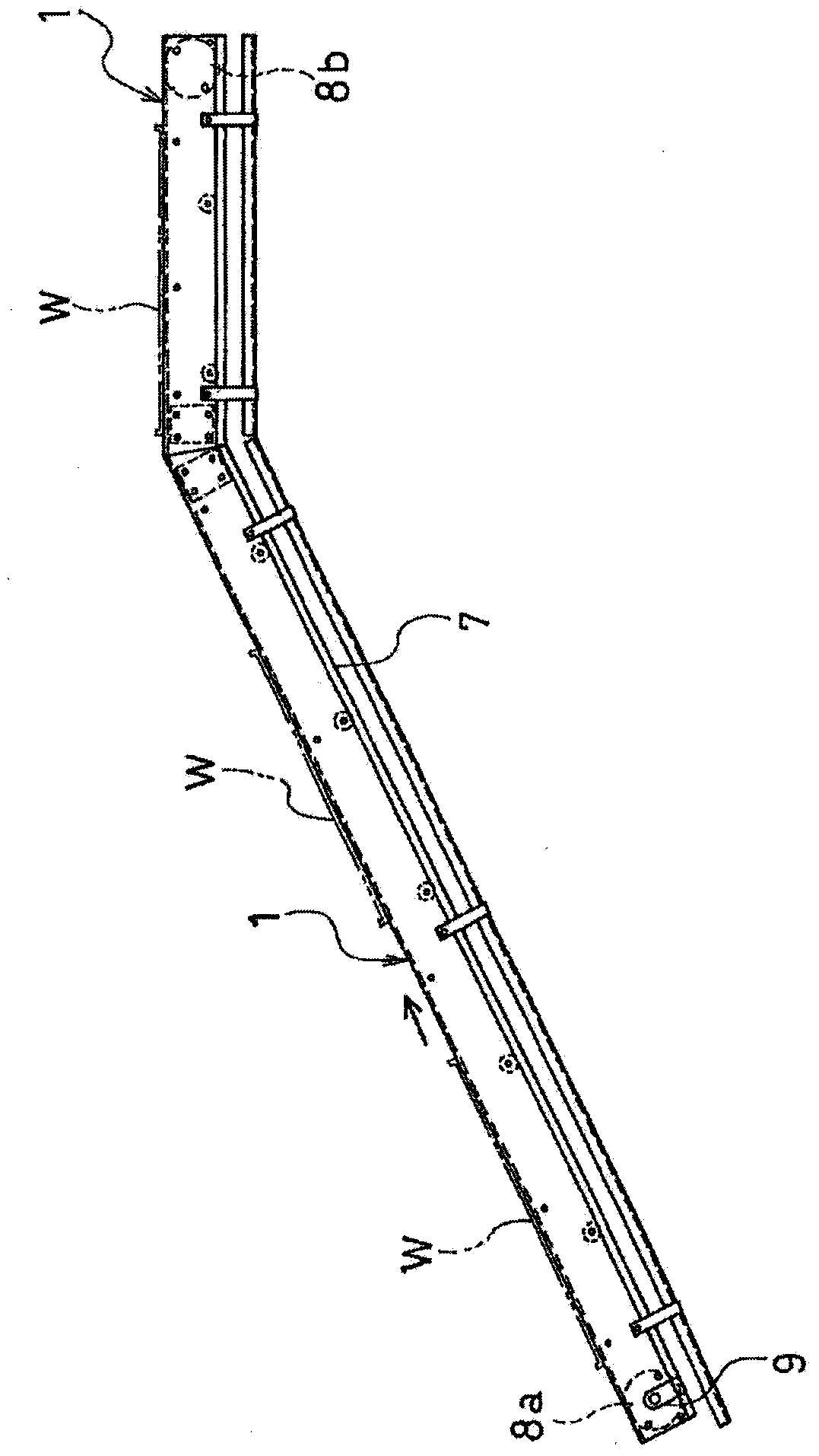
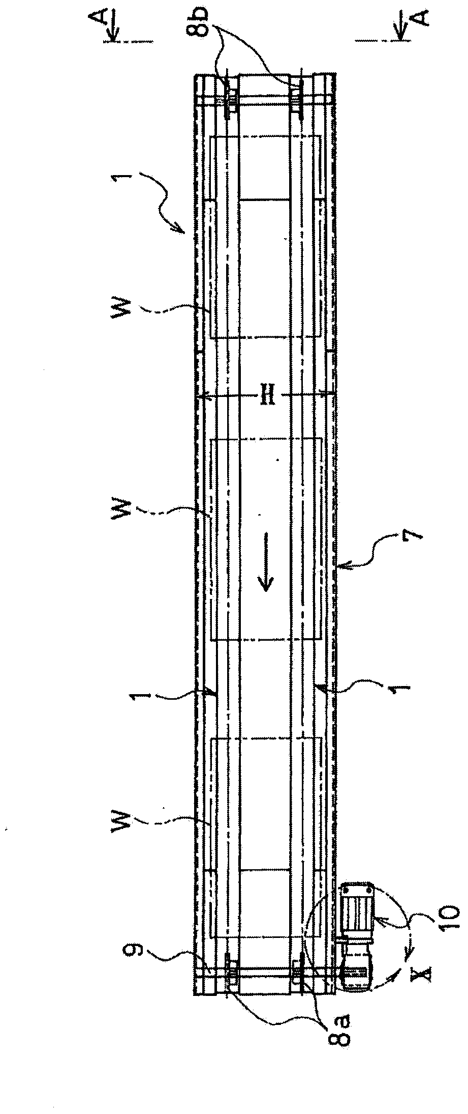
[0026] A scheme embodying the plastics chain conveyor of feature of the present invention is as Figure 1-9 shown. The plastic chain conveyor 1 is mounted on a steep slope (for example with an inclination angle of 30°-60°), but the invention is not limited to steep slopes: it is also possible to mount the conveyor in a horizontal position.

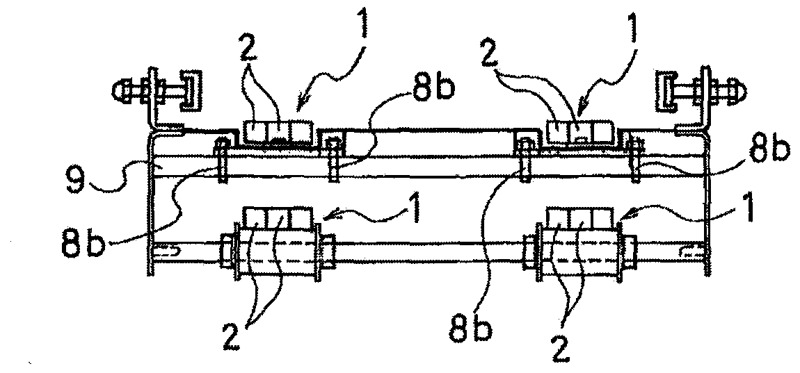
[0027] in such as Figure 5-7 In the shown plastic chain conveyor 1, the front and rear ends 2a, 2b of the plastic chain modules 2 made of plastic material (such as acetal (acetal)) pass through a plurality of plastic connecting pins 3a (such as with round A rod-shaped connecting pin made of nylon with a circular cross-section) and a metal connecting pin 3b (in this example a rod-shaped connecting pin made of a radial bipolar neodymium magnet with a circular cross-section) are rotatably coupled so that Form a predetermined length of endless plastic chain conveyor.

[0028] In the plastic chain module 2 of the plastic chain conveyor 1, t...


PUM


Abstract

Front and back ends (2a, 2b) of plastic chain modules (2) made of a plastic material are rotatably linked by multiple plastic connecting pins (3a) and metal connecting pins (3b) to form an endless plastic chain conveyor (1). In the plastic chain modules (2) of the plastic chain conveyor (1), carrier surfaces (4a) (top surfaces) of module bodies (4) are smooth. Offset engaging parts (5a, 5b) that can be attached to and detached from each other in the width direction of the plastic chain conveyor (1) are formed on linking end pieces (4X) of the module bodies (4). Circular through-holes (6) receiving the bar-shaped connecting pins (3a, 3b) that rotatably link the offset engaging parts (5a, 5b) of the chain modules (2) are formed at the centers of the sides of the offset engaging parts (5a, 5b).

Description

technical field [0001] The present invention relates to a plastic chain conveyor for carrying metal trays on which food material such as bread, sweets etc. is placed. More specifically, the present invention relates to a plastic chain conveyor along a particularly steeply inclined conveyor line capable of transporting metal pallets and the like in a steady state without causing them to slip and fall or become out of alignment . Background technique [0002] Typically, in a manufacturing process for food such as bread or confectionery, a predetermined length of carriage conveyors (such as chain conveyors, belt conveyors, roller conveyors, etc.) are used to convey the metal on which the food material is placed A carrier (such as a disc or plate). The metal pallets are loaded onto and carried on a pallet conveyor. [0003] In the bread making process, especially in the rack paths (such as tunnel ovens, etc.) Chain conveyors are linked to predetermined lengths and placed int...

Claims


Application Information

Patent Timeline
Patent Type & Authority Applications(China)
IPC IPC(8): B65G15/00
CPCB65G17/08B65G15/32
Inventor 宫下通武
Owner LAITRAM LLC
Why Eureka
Try Eureka