Long cantilever upper pier structure and method for medium and long span steel beam incremental launching construction

A technology of jacking construction and long cantilever, applied in the direction of bridges, bridge construction, erection/assembly of bridges, etc., can solve the problems of lack of jacking method and upper pier, difficult unloading, transportation, high temporary pier cost, etc., to achieve good economy performance and operability, easy access to equipment, and convenient construction

Pending Publication Date: 2022-03-29
CHINA POWER CONSRTUCTION GRP GUIYANG SURVEY & DESIGN INST CO LTD
View PDF2 Cites 0 Cited by
  • Summary
  • Abstract
  • Description
  • Claims
  • Application Information

AI Technical Summary

Problems solved by technology

When the bridge site is located in a mountainous area with a large terrain height difference, the cost of setting up a high temporary pier in front of the pushing platform is too high. The setting of the steel guide beam will be affected by the tunnel, making it difficult to unload and transport
[0006] For the construction of medium and long span steel girder bridges under the above special conditions, there is still a lack of a jacking method and pier-up technology without guide beams and temporary piers.

Method used


Image

  • Long cantilever upper pier structure and method for medium and long span steel beam incremental launching construction
  • Long cantilever upper pier structure and method for medium and long span steel beam incremental launching construction
  • Long cantilever upper pier structure and method for medium and long span steel beam incremental launching construction

Examples


Embodiment 1

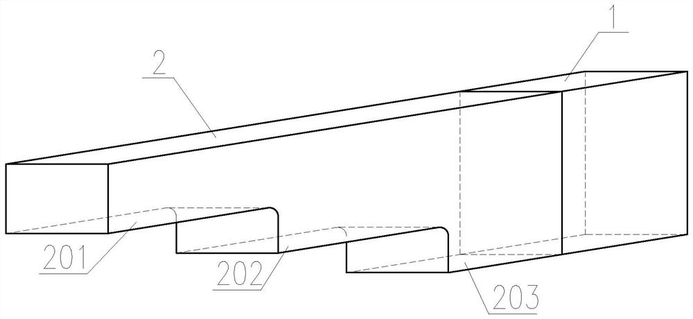
[0034] see Figure 1-6 As shown, in this embodiment, the span of the steel beam 1 is 70m, and the length of the nose bridge 2 is 4m. Its implementation process includes the following steps:

[0035] S1 as figure 1 As shown, a nose bridge 2 is used as an auxiliary structure for the upper pier of the steel beam, and then the setting of the long steel guide beam is banned. In this embodiment, the root section of the nose bridge 2 is the same as that of the steel beam 1, and the height of the nose bridge gradually changes in a trapezoidal shape from the root , three steps are set, the third step 203 of the nose bridge is flush with the bottom of the steel beam, and the roots of the nose bridge 2 and the web of the steel beam 1 are connected by bolt welding to form an integral structure.

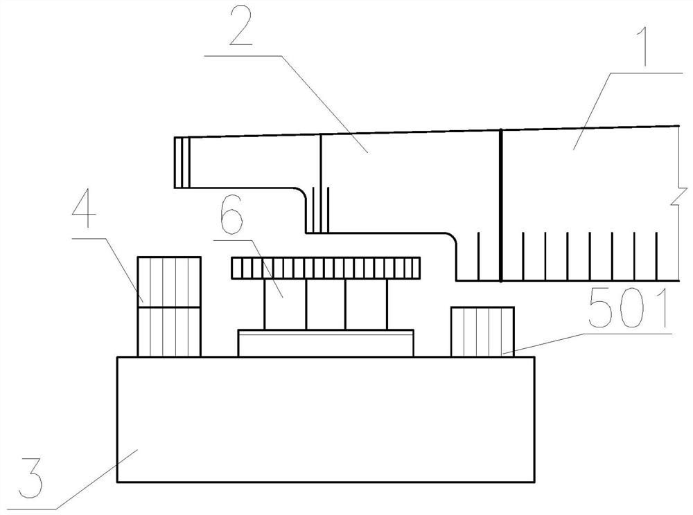
[0036] S2 as figure 2As shown, the steel beam 1 with the nose bridge 2 is pushed forward to the front end of the distribution beam 3 on the top of the next pier by using the conventional push...


PUM


Abstract

The long cantilever upper pier structure comprises an upper pier nose bridge, the length of the upper pier nose bridge is 3-5 m, the root section of the nose bridge is the same as the section of the steel beam, the height of the nose bridge gradually changes from the root in a trapezoidal mode, and the root of the nose bridge is connected with a steel beam web in a bolting and welding mode; a jack is arranged on a steel cushion block at the front end of a pier top distribution beam, when the front section of a nose bridge crosses walking type pushing equipment, a first step at the front end of the nose bridge is jacked up to a certain height through the jack on the steel cushion block, a steel cushion block is additionally arranged at the rear end, meanwhile, a supporting stack is cushioned between the nose bridge and the walking type pushing equipment, and the jack falls back; and normal steel beam pushing is conducted in cooperation with a pushing platform at the bridge head and walking type pushing equipment arranged at the pier top, and non-guide-beam and non-temporary-pier pushing construction of the whole long cantilever steel beam is completed. The buckle cable tower is arranged on the steel beam, when a conventional nose bridge pier mounting measure cannot meet the requirement, the front section of the main beam is pulled up through the tower inhaul cable, and smooth pier mounting of the steel beam is guaranteed.

Description

technical field [0001] The invention belongs to the field of bridge superstructure construction, and relates to a long cantilever upper pier structure and a method thereof for the push construction of a medium-long span steel girder. Background technique [0002] The traditional jacking process commonly used in bridge construction is the dragging multi-point continuous jacking method (hereinafter referred to as the dragging method). The dragging method pulls the steel strand by tensioning the continuous jacks set on each temporary pier, and drags the beam section. Slip on the slideway set on the top of the temporary pier, and the traction beam body is installed in place. The drag-type multi-point continuous jacking is the most widely used. This method has mature technology, low construction cost and low requirements on equipment. Walking jacking has certain advantages over traditional dragging jacking. It has higher applicability and safety for beam jacking of some overpass...

Claims


Application Information

Patent Timeline
Patent Type & Authority Applications(China)
IPC IPC(8): E01D21/06E01D21/00
CPCE01D21/06E01D21/00
Inventor 祁义辉张丙文张昱
Owner CHINA POWER CONSRTUCTION GRP GUIYANG SURVEY & DESIGN INST CO LTD
Why Eureka
Try Eureka