This helps you quickly interpret patents by identifying the three key elements:
Problems solved by technology
Method used
Benefits of technology
Problems solved by technology
[0004] This device has the following defects: separate design, many parts, large volume, loose structure, large pipe consumption and valve loss, low gas output rate per unit power, complex control circuit, difficult synchronous control, poor reliability, and high cost
Method used
Image
Click on the blue label to locate the original text in one second.
Reading with bidirectional positioning of images and text.
Examples
Embodiment example 1
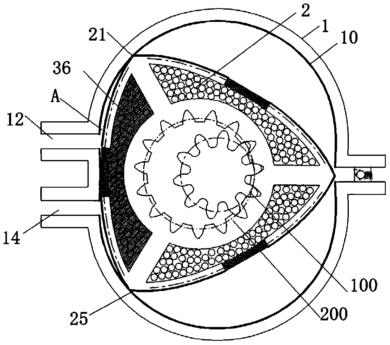
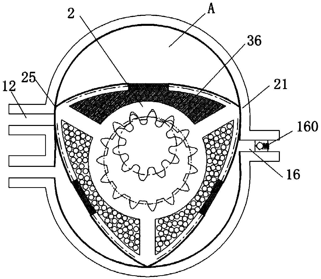
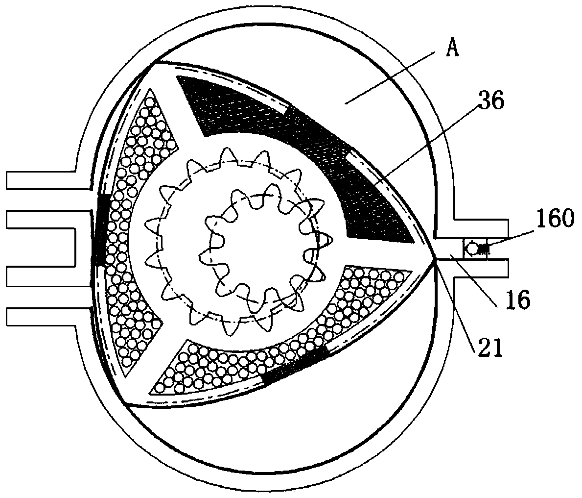
[0041] Figure 1-1 to Figure 1-6 It is a structural schematic diagram of the pressure swing adsorption device of the present invention, referring to Picture 1-1 , a pressure swing adsorption device, comprising: a housing 1, a rotor 2, an adsorption chamber 32, an adsorption chamber 34, and an adsorption chamber 36, wherein the inner surface 10 of the housing 1 is an arc surface, and its arc trajectory is obtained by the following equation:
[0042] x=R*cosα+e*cos3α;
[0043] y=R*sinα+e*sin3α;
[0044] α∈[0°, 360°]e=1.5R=10
[0045] The casing is provided with an air inlet 12 , an air outlet 14 and an air outlet 16 , and the air outlet 16 is used to discharge the separated gas. The contour of rotor 2 is obtained by the following equation:
[0046] e=1.5R=10
[0047] v=30+t*60
[0048] d=-3*e*sin(3*v) / R
[0049] u=2*v-asin(d)
[0050] x=2*e*cos(u)*cos(3*v)+R*cos(2*v)
[0051] y=2*e*sin(u)*cos(3*v)+R*sin(2*v)
[0052] The rotor 2 is arranged in the casing 1 and is rota...
Embodiment example 2
[0066] Figure 2-1 to Figure 2-8 It is a structural schematic diagram of the pressure swing adsorption device of the present invention, referring to diagram 2-1 , a pressure swing adsorption device, comprising: a housing 10, a rotor 20, an adsorption chamber 320, an adsorption chamber 340, an adsorption chamber 360, and an adsorption chamber 380, wherein the inner surface 100 of the housing 10 is an arc surface, and its arc trajectory is obtained by the following equation :
[0067] x=e*cos(α)+R*cos(α / 4)
[0068] Y=e*sin(α)+R*sin(α / 4)
[0069] α∈[0°, 360°], e is the eccentricity, e=12, R is the creation radius, R=96.
[0070] The casing is provided with an air inlet 120, a second exhaust port 140, a first exhaust port 160, and an air outlet 180, and the air outlet 180 is used to discharge the separated gas; the outline of the rotor 20 is obtained by the following equation:
[0071] x r =e*cosβ+e*cos(α-β / 3)+R*cos(α / 4-β / 3)
[0072] the y r =e*cosβ+e*sin(α-β / 3)+R*sin(α / 4-...
PUM
Abstract
The invention discloses a pressure swing adsorption device which comprises a shell, a rotor and an absorption chamber, wherein the inner surface of the shell is arc-shaped; the shell is provided with at least one air inlet, at least one air exhaust and at least one air outlet; the rotor is arranged inside the shell; at least two contact ends which are constantly in sliding contact with the inner surface of the shell are arranged on the rotor; independent chambers, namely, air chambers, are formed by the outer surface of the rotor and the inner surface of the shell between adjacent contact ends; the air chambers are partitioned by the contact ends; the absorption chamber is arranged inside the rotor, serves as a part of the rotor and rotates together with the rotor; molecular sieves are filled into the absorption chamber; the absorption chamber is provided with sieve holes so as to be communicated with the air chambers. The pressure swing absorption device has the advantages that the structure is simple and compact, no complex air pipelines are needed, the synchronization is simple to control, and corresponding electromagnetic valves and complex control circuits of the electromagnetic valves in the conventional device are saved.
Description
technical field [0001] The invention relates to a pressure swing adsorption device, which is mainly used in the technical field of gas medium separation. Background technique [0002] Pressure swing adsorption (referred to as PSA), as a gas separation technology, has attracted the attention of the industrial circles of various countries, and has developed rapidly. Its working principle is: use the difference in the "adsorption" performance of the adsorbent molecular sieve to different gas molecules to separate the gas mixture, after the adsorption balance, according to the different characteristics of the adsorption amount of the molecular sieve at different pressures, reduce the pressure to make the molecular sieve release the adsorption. The adsorption of gas, this process is called regeneration. At present, pressure swing adsorption devices usually use two or more towers connected in parallel, so that pressure adsorption and decompression regeneration can be performed al...
Claims
Application Information
Patent Timeline
Application Date:The date an application was filed.
Publication Date:The date a patent or application was officially published.
First Publication Date:The earliest publication date of a patent with the same application number.
Issue Date:Publication date of the patent grant document.
PCT Entry Date:The Entry date of PCT National Phase.
Estimated Expiry Date:The statutory expiry date of a patent right according to the Patent Law, and it is the longest term of protection that the patent right can achieve without the termination of the patent right due to other reasons(Term extension factor has been taken into account ).
Invalid Date:Actual expiry date is based on effective date or publication date of legal transaction data of invalid patent.
