Stirring machine

A mixer and mixing barrel technology, which is applied to mixer accessories, mixers, mixers with rotating containers, etc., can solve the problems that mixing cannot meet its requirements, and achieve precise temperature control, quality and efficiency improvement, and production efficiency. Effect

Active Publication Date: 2013-12-11
昆山奥泰克自动化科技有限公司
View PDF5 Cites 7 Cited by
  • Summary
  • Abstract
  • Description
  • Claims
  • Application Information

AI Technical Summary

Problems solved by technology

[0002] Existing mixers generally rotate the shaft with blades in a cylinder or tank to stir and mix one or more materials to make them have a suitable consistency or mix them into a mixture. Usually, the shaft with blades is set to be able to Rotating, and the cylinder or tank is set to be fixed. Although the structure is relatively simple and the installation is more convenient, this kind of mixer is only suitable for mixing materials with relatively low requirements, and cannot meet the requirements for mixing some materials with relatively high requirements. its requirements

Method used


Image

  • Stirring machine
  • Stirring machine
  • Stirring machine

Examples


Embodiment 1

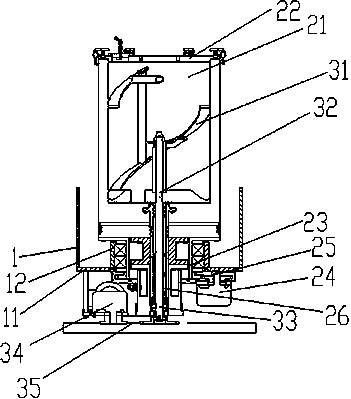
[0030] see figure 1 , as shown in the legend therein, a mixer includes a support 1, a mixing bucket mechanism and a mixing blade mechanism, the above mixing bucket mechanism includes a barrel body 21 for holding materials, a sealing barrel body 21 A barrel cover 22, a first rotating shaft 23 fixedly connected to the lower side of the barrel body 21, a first motor 24 for providing the first power, and a first gear for transmitting the first power to the first rotating shaft 23 Transmission system 25; above-mentioned stirring fan mechanism comprises a fan blade 31 for stirring above-mentioned material, the stirring shaft 32 of support fan blade 31, the second rotating shaft 33 that is fixedly connected to the lower end of stirring shaft 32, for providing A second motor 34 for the second power and a second gear transmission system 35 for transmitting the second power to the second rotating shaft 33; the support plate 11 is fixedly installed on the support plate 1; the collar 12 i...

Embodiment 2

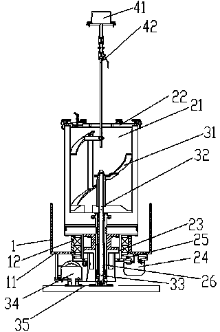
[0034] see figure 2 , as shown in the legend therein, the rest are the same as in the embodiment 1, the difference is that the above-mentioned mixing tank is also provided with an additive adding device, and the above-mentioned additive adding device includes an additive storage area 41 for storing additives and for adding to The additive feeding pipe 42 for feeding additives into the barrel body 21 ; the additive storage area 41 is arranged above the barrel body 21 ; the additive feeding pipe 42 connects the additive storage area 41 and the barrel body 21 .

[0035] During the stirring process, additives can be added to the barrel body 21 at any time, and the additives to be added are placed in the additive storage area 41, and the additives are passed into the material of the barrel body 21 through the additive feeding pipe 42, and fully mixed and stirred with the material , the amount and speed of addition of additives can be adjusted during this process.

Embodiment 3

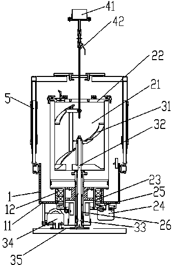
[0037] see image 3 , as shown in the legend therein, the rest are the same as the embodiment 2, the difference is that the above-mentioned mixing bucket is also provided with an oil cylinder 5 for opening or closing the bung 22, and one end of the oil cylinder 5 is arranged on the support 1; The other end of the oil cylinder 5 is connected to the bung 22 and lifts or presses the bung 22 on the bucket body 21 .

[0038] The oil cylinder 5 can press the bung 22 to seal the bucket body 21, and can automatically open the bung 22, which reduces the waste of manpower and improves the production efficiency.


PUM


Abstract

The invention discloses a stirring machine. The stirring machine comprises a support, a stirring barrel mechanism as well as a stirring fan blade mechanism, wherein the stirring barrel mechanism comprises a stirring barrel for containing materials and a first power drive device for rotating the stirring barrel around the axis; the stirring fan blade mechanism comprises a stirring fan blade for stirring materials and a second power drive device for rotating the stirring fan blade; the stirring barrel is fixedly installed on the support and can rotate relative to the support; the stirring fan blade is fixedly installed in the stirring barrel and can rotate relative to the stirring barrel; the rotational directions of the stirring barrel and the stirring fan blade are opposite. The stirring barrel and the stirring fan blade in the stirring machine are both arranged to be rotatable, and the speed can be regulated; when the fan blade rotates for stirring, the barrel body rotates in the corresponding opposite direction, and the stirring quality and the stirring efficiency can be improved greatly.

Description

technical field [0001] The invention relates to a mixer. Background technique [0002] Existing mixers generally rotate the shaft with blades in a cylinder or tank to stir and mix one or more materials to make them have a suitable consistency or mix them into a mixture. Usually, the shaft with blades is set to be able to Rotating, and the cylinder or tank is set to be fixed. Although the structure is relatively simple and the installation is more convenient, this kind of mixer is only suitable for mixing materials with relatively low requirements, and cannot meet the requirements for mixing some materials with relatively high requirements. its requirements. Contents of the invention [0003] In order to solve the above problems, the object of the present invention is to provide a mixer capable of improving stirring quality and stirring efficiency. [0004] In order to achieve the above object, the technical solution of the present invention is: a mixer, including a brack...

Claims


Application Information

Patent Timeline
Patent Type & Authority Applications(China)
IPC IPC(8): B01F9/12B01F15/02B01F29/83
Inventor 徐爱新朱国辉
Owner 昆山奥泰克自动化科技有限公司
Why Eureka
Try Eureka