Special automatic cleaning instrument for low-voltage direct current electromagnetic pulse-type contact lenses

An electromagnetic pulse and contact lens technology, which is applied in the directions of cleaning methods, chemical instruments and methods, cleaning methods and utensils using liquids, etc., can solve the problems of matching cleaning effects, etc., and achieves easy portability, strong decontamination ability, and small size. Effect

Active Publication Date: 2013-12-11
杭州视亨光电有限公司
View PDF14 Cites 10 Cited by
  • Summary
  • Abstract
  • Description
  • Claims
  • Application Information

AI Technical Summary

Problems solved by technology

Generally speaking, its cleaning effect is diff

Method used


Image

  • Special automatic cleaning instrument for low-voltage direct current electromagnetic pulse-type contact lenses
  • Special automatic cleaning instrument for low-voltage direct current electromagnetic pulse-type contact lenses
  • Special automatic cleaning instrument for low-voltage direct current electromagnetic pulse-type contact lenses

Examples


Embodiment 1

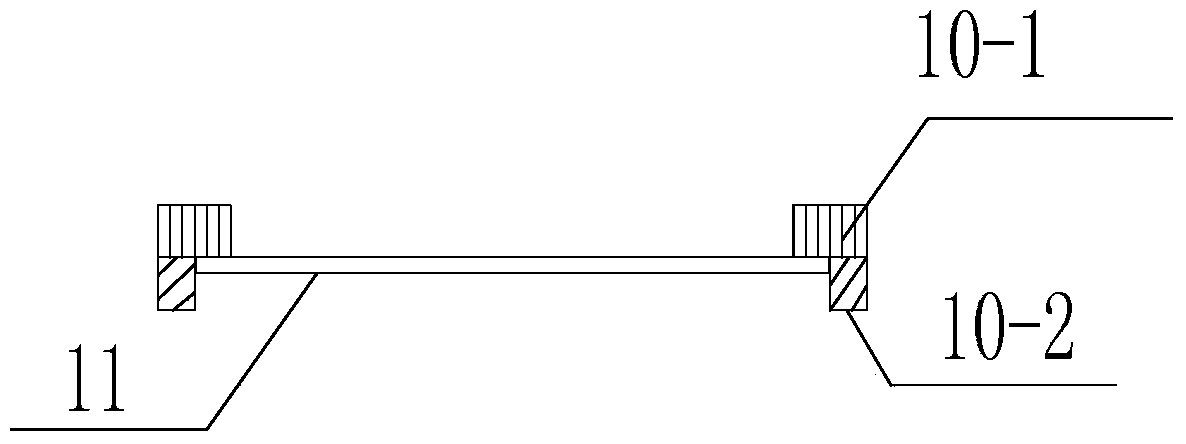
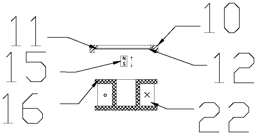
[0052] Example 1 As shown in Figures 3(a), 3(b), 3(c), and 3(d),

[0053] As shown in Figure 3(a), the power part includes a magnetic steel column 15, a coil frame 16, a coil 22, a copper sheet and a first pressing plate, and the copper sheet is a permanent magnet; the copper sheet is arranged on the nano-silver pad and the first pressing plate Between, the cross section of the bobbin is U-shaped, the coil is wound on one end of the U-shaped bobbin, and the bobbin is set in the raised through groove of the first pressure plate, and the U-shaped opening end corresponds to the copper sheet; the through groove of the first pressure plate A second pressing plate is arranged on the top, and the second pressing plate is fixedly connected with the first pressing plate, and the inner side wall of the through groove of the first pressing plate and the upper surface of the second pressing plate form a cavity for placing the coil skeleton.

Embodiment 2

[0055] As shown in Figure 3(b), the power part includes a magnetic steel column 15, a coil bobbin 16, a coil 22, a magnetic steel column, a copper sheet, and a first pressure plate, and the magnetic steel column is a permanent magnet, and one end of the magnetic steel column is connected to the bottom of the copper sheet. The surface is fixed; the copper sheet is set between the nano-silver pad and the first pressure plate, the section of the coil frame is a cylinder, the coil is wound on the outer wall of the coil frame, and the coil frame is set in the raised channel of the first pressure plate, and the copper sheet Correspondingly: a second pressure plate is provided on the first pressure plate through groove, the second pressure plate is fixedly connected with the first pressure plate, and the inner side wall of the first pressure plate through groove and the upper surface of the second pressure plate form a cavity for placing the coil skeleton.

Embodiment 3

[0057] As shown in Figure 3(c) and 3(d), the power part includes a magnetic steel column 15, a coil bobbin 16, a coil 22, a magnetic steel column, a copper sheet and a first pressure plate, and the copper sheet is arranged on the nano-silver pad and the first Between the pressure plates, one end of the magnetic steel column is fixed to the lower surface of the copper sheet; the coil frame is a cylinder or its cross-section is mountain-shaped, and its material is metal; the coil is wound on the coil frame, and the coil frame is arranged on the first pressure plate In the through groove raised, corresponding to the copper sheet; the second pressure plate is arranged on the first pressure plate through groove, the second pressure plate is fixedly connected with the first pressure plate, and the inner side wall of the first pressure plate through groove is formed with the upper surface of the second pressure plate. The cavity for placing the bobbin.


PUM


Abstract

The invention relates to a special automatic cleaning instrument for low-voltage direct current electromagnetic pulse-type contact lenses. The cleaning instrument comprises a movable upper cover and a shell, wherein the movable upper cover is movably connected with the shell; the shell comprises a fixing plate and a lower bottom cover; the fixing plate is fixedly connected with the lower bottom cover; a control circuit, a power part and a cleaning part are arranged in the shell; and a USB charging port is formed on the lower bottom cover. The special automatic cleaning instrument is smaller in size and more convenient to carry, and the cleaning instrument avoids a problem of a No.7 dry battery which is frequently changed and is more environment-friendly; the cleaning instrument is stronger in dirt-removing power, and is specifically suitable for cleaning various contact lenses; and the cleaning instrument can guarantee perfect combination of damping variable frequency ultrasonic and button battery, a USB charger and sharp vibrating energy irreproachably.

Description

technical field [0001] The invention belongs to the technical field of corneal contact lens care, and in particular relates to a special automatic cleaning instrument for low-voltage DC electromagnetic pulse contact lenses. Background technique [0002] After various contact lenses enter the market, the frequent cycle of "cleaning-use-cleaning-use" of various contact lenses is becoming more and more cumbersome. At the same time, whether this cycle is reasonable or not has become very important and urgent. . Especially if the contact lens is cleaned thoroughly during the cleaning process [0003] Cleanliness becomes even more important. If the cleaning is not thorough, it will not only cause corneal inflammation, but also reduce the light transmittance of the contact lens, hindering the normal use of the user. Looking at all kinds of cleaning devices for contact lenses on the market, water or care solution is used as the cleaning source, plus a fixed frequency ultrasonic ...

Claims


Application Information

Patent Timeline
IPC IPC(8): B08B3/12
Inventor 赵德荣汪治芮冰如周勇梅宝山李南希
Owner 杭州视亨光电有限公司
Why Eureka
Try Eureka