Wing surface punching device of automobile U-shaped beam

A punching device, U-shaped technology, applied in the field of plate processing devices, can solve problems affecting processing, affecting feeding, accumulation, etc.

Active Publication Date: 2013-12-11
JIANGSU JINFANGYUAN CNC MACHINE CO LTD
View PDF6 Cites 3 Cited by
  • Summary
  • Abstract
  • Description
  • Claims
  • Application Information

AI Technical Summary

Problems solved by technology

This device can process both sides of the airfoil at the same time, and can avoid multiple clamping. The waste cannot be dropped norma

Method used


Image

  • Wing surface punching device of automobile U-shaped beam
  • Wing surface punching device of automobile U-shaped beam

Examples


Embodiment Construction

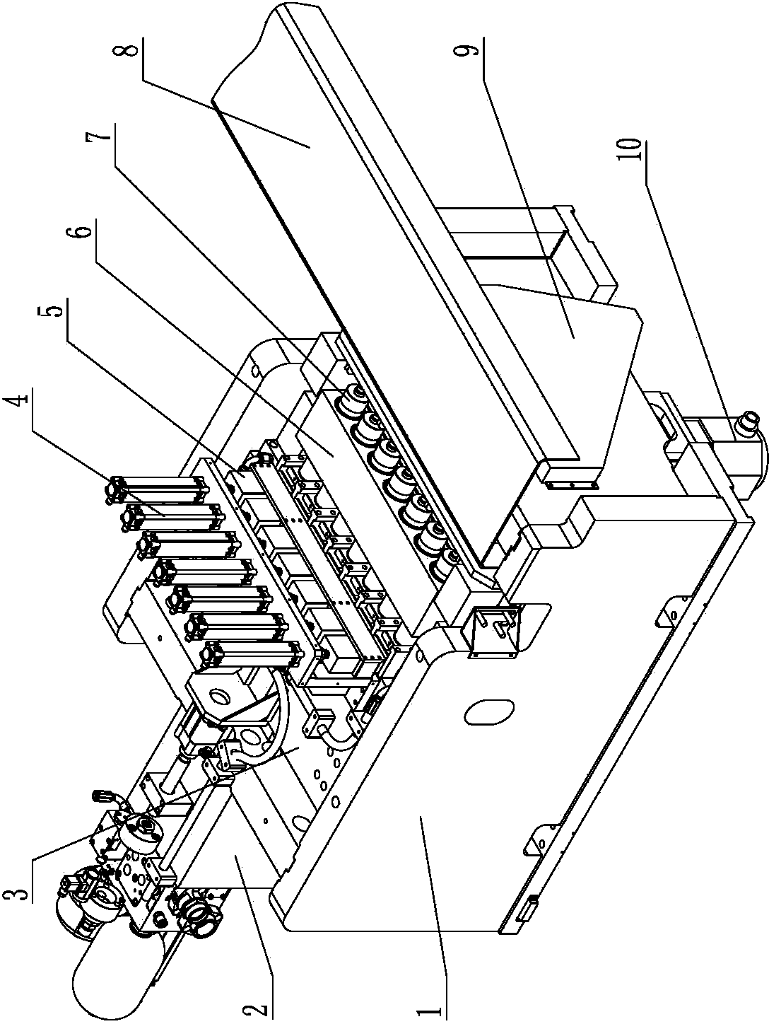
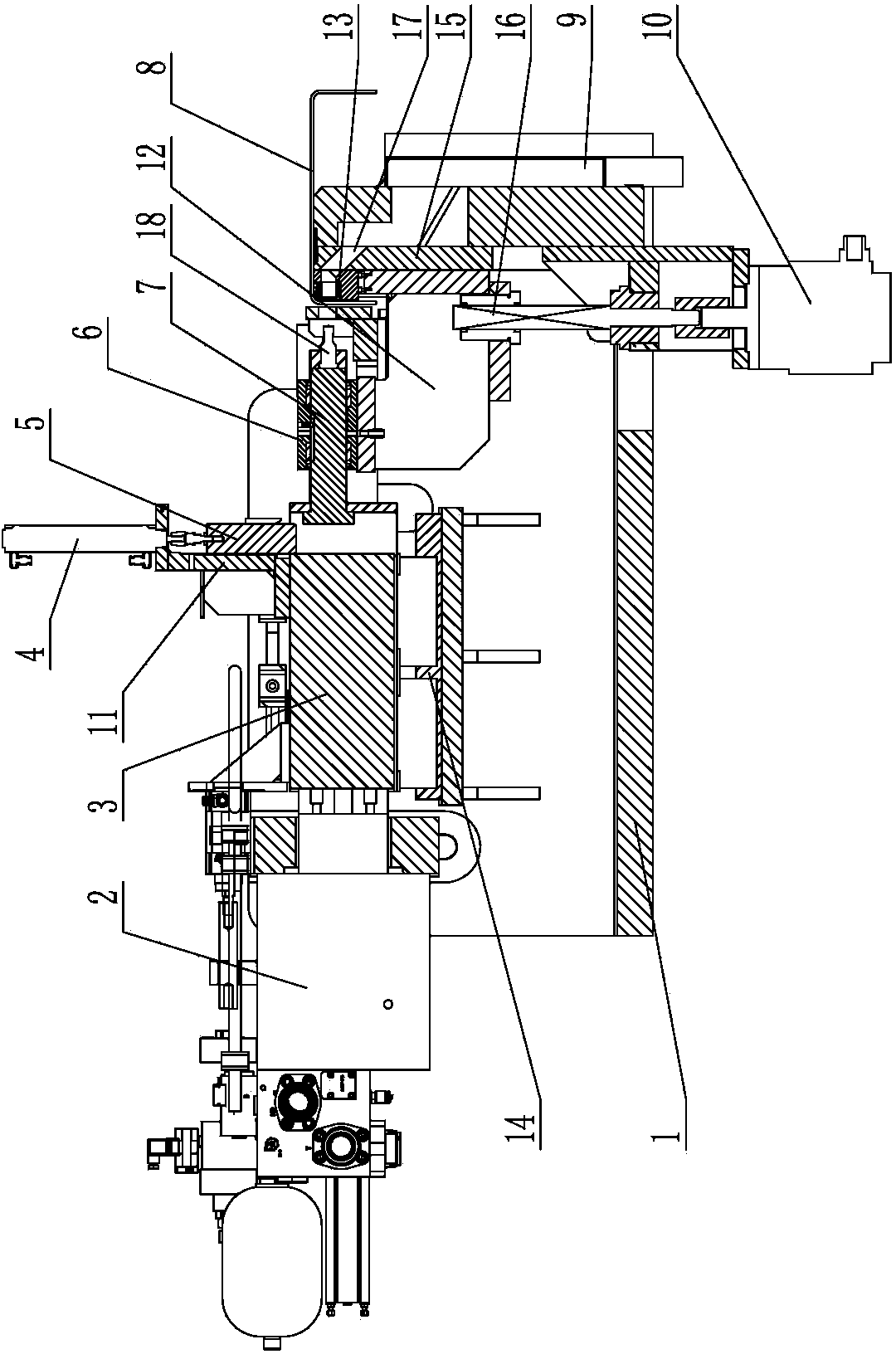
[0011] Such as figure 1 with 2 Shown, is a kind of automobile U-beam airfoil punching device, comprises frame 1, is provided with guide rail 14 horizontally on frame 1, is provided with main slider 3 that can slide along guide rail 14 in guide rail 14, and main slider 3 is provided with a hydraulic punch 2 at one end, and the other end of the main slider 3 is correspondingly provided with a mold assembly, the mold assembly includes a corresponding number of punches 18 and dies 13, and the punches 18 are arranged in the punch guide seat 6, The punch guide seat 6 is slidingly provided with a punch push rod 7, and the punch push rod 7 is in contact with one end of each punch 18 one by one, and the punch guide seat 6 and each die 13 are installed on the die holder bracket 12 , the main slider 3 is fixed with a cylinder bracket 11, and several mold selection cylinders 4 are vertically arranged side by side on the cylinder bracket 11, and the piston rod of the mold selection cylind...


PUM


Abstract

The invention discloses a wing surface punching device of an automobile U-shaped beam, and belongs to the field of punching machine tools. The wing surface punching device of the automobile U-shaped beam comprises a main sliding block arranged on a machine frame. A die assembly is arranged corresponding to the main sliding block, the die assembly comprises a plurality of male dies and a plurality of female dies which correspond to one another, and the male dies are arranged inside a male die guide holder. Male die push rods which abut against one ends of the male dies respectively are arranged inside the male die guide holder. The male die guide holder and the female dies are mounted on a die holder support. The main sliding block is fixedly connected with a cylinder support, the cylinder support is provided with a plurality of die selection cylinders, the lower ends of piston rods of the die selection cylinders are connected with die selection push blocks, and the die selection push blocks are correspondingly arranged between the sliding block and the male dies. A die set guide plate is arranged at the position, corresponding to the side face of the die holder support, of the machine frame. A blanking channel is arranged in the position, corresponding to the positions of the female dies, of the die set guide plate. A lifting motor is arranged on the lower side of the die holder support on the machine frame, and the upper end of a spindle of the lifting motor is connected with the bottom of the die holder support through a ball screw mechanism. By means of the wing surface punching device of the automobile U-shaped beam, waste blanking is convenient, feeding can not be affected, and machining energy consumption is low.

Description

technical field [0001] The invention relates to a plate processing device, in particular to a punching device for a U-shaped beam of an automobile. Background technique [0002] The U-shaped beam is an important part on the chassis of the car. The section of the U-shaped beam is U-shaped, and various holes are processed on the two wing surfaces of the U-shaped beam and the belly surface; The equipment for punching holes on the belly and airfoil usually punches the holes on the belly of the U-shaped beam on one piece of equipment, and then switches the U-shaped beam to another equipment, and then punches out the holes on the airfoil. In the prior art, there is a U-shaped beam airfoil punching machine tool. Its structure mainly includes guide rails arranged on the frame. The main engine carriage slides and is arranged on the guide rails. Punch assembly; the center pad is located on the upper part of the workbench and is fixedly connected with the vertical plates on both sides...

Claims


Application Information

Patent Timeline
IPC IPC(8): B21D28/32B21D43/20B21D28/34
Inventor 王爱民叶敬春李强王雪徐成
Owner JIANGSU JINFANGYUAN CNC MACHINE CO LTD
Why Eureka
Try Eureka