Wire drawing device for metal wire

A wire-pulling device and metal wire technology, applied in the field of metal material processing, can solve problems such as time-consuming, labor-intensive, and inability to guarantee quality.

Active Publication Date: 2013-12-11
安徽皖南新维电机有限公司
View PDF7 Cites 23 Cited by
  • Summary
  • Abstract
  • Description
  • Claims
  • Application Information

AI Technical Summary

Problems solved by technology

The way of manual operation is time-consuming and labor-intensive, and the quality cannot be guaranteed

Method used


Image

  • Wire drawing device for metal wire
  • Wire drawing device for metal wire
  • Wire drawing device for metal wire

Examples


Embodiment Construction

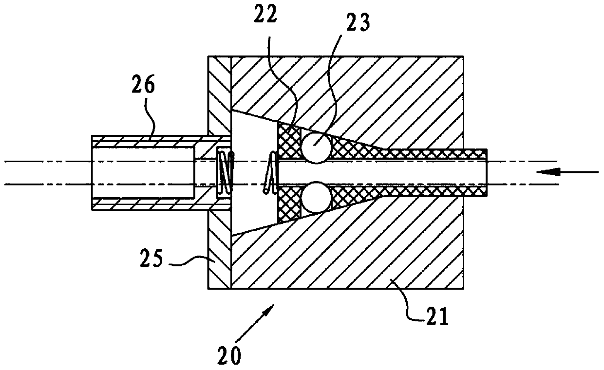
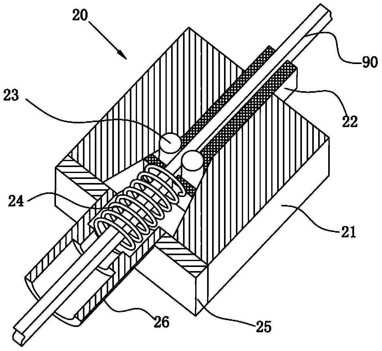
[0012] figure 1 , 5 , The direction indicated by the arrow in 6 is the feeding direction of the metal wire.

[0013] Such as figure 1 , 5 As shown, a metal wire pulling device includes two clamping units 20 arranged on the frame 10, and the two clamping units 20 are arranged in sequence, wherein at least one clamping unit is mobile and the moving direction is the same as the metal to be conveyed The running direction of the thread is the same, and the thread clamping unit 20 is provided with a one-way thread-feeding reverse non-return mechanism. The wire harness 90 can only be fed in one direction in the clamping unit 20, and self-locking will occur when it moves in the opposite direction, so the relative movement between two clamping units 20 arranged in the same direction can make the wire harness 90 move in one direction For this reason, the outlet direction of the clamping unit 20 is defined as the front of the clamping unit 20. One clamping unit 20 is fixed, and when ...


PUM


Abstract

The invention belongs to the field of metal material processing, in particular to a wire drawing device for a metal wire. The wire drawing device for the metal wire comprises a rack, two wire clamping units are arranged on the rack, the two wire clamping units are arranged front and back, at least one wire clamping unit is movable, the moving direction of at least one wire clamping unit is identical with the advancing direction of the metal wire to be conveyed, and one-way wire feeding reverse non-return mechanism are arranged in the wire clamping units. Due to the adoption of the technical scheme, the two wire clamping units achieve traction feeding and guide limiting on the metal wire through the mutual cooperation of relative movement and clamping and loosening movement, the efficiency that feeding is carried out on the wire to facilitate cutting is improved, and the quality of the wire is ensured.

Description

technical field [0001] The invention belongs to the field of metal material processing, and in particular relates to a metal wire pulling device. Background technique [0002] Metal wires have been widely used as conductors. For example, a large number of metal wires or enameled wires are used in the field of electromechanical equipment production. Since the motor winding needs to use a large amount of enameled wire, and the length of each enameled wire is required to be roughly equal, but most of the finished enameled wires are wound into bundles of a whole enameled wire, so it needs to be cut to a suitable length when used. In the prior art, the manual method is basically used for traction, and after the required length is measured, it is manually cut. The way of manual operation is time-consuming and labor-intensive, and the quality cannot be guaranteed. Contents of the invention [0003] The object of the present invention is to provide a wire pulling mechanism capab...

Claims


Application Information

Patent Timeline
Patent Type & Authority Applications(China)
IPC IPC(8): B21F23/00
Inventor 刘永健程润生潘晋
Owner 安徽皖南新维电机有限公司
Why Eureka
Try Eureka