Underwater floating body and installing method thereof

An installation method and floating body technology, which are applied in the directions of underwater ships, underwater operation equipment, floating buildings, etc., can solve problems such as difficulty in implementation, and achieve the effects of strong installation controllability, prolonged service life, and convenient adjustment.

Active Publication Date: 2013-12-11
WUCHANG SHIPBUILDING IND
View PDF6 Cites 8 Cited by
  • Summary
  • Abstract
  • Description
  • Claims
  • Application Information

AI Technical Summary

Problems solved by technology

However, due to the limited pressure bearing capacity of the floating body structure, the process of inflating the floating body must be carried out step by step, that is, the pressure and balance adjustment must be carried out every time a certain water level is reached. For example, the working water depth of an underwater floating body is about 300 meters. Calculated by performing such an operation every 5 meters (according to the setting of the pressure resistance capacity of the floating body), then the entire installation process requires dozens of such operations of pressure adjustment and underwater attitude adjustment of the floating body
In addition, the traditional underwater floating body installation process is completed underwater through the control system with the help of the underwater operating system (ROV), so the installation process is difficult to achieve

Method used


Image

  • Underwater floating body and installing method thereof
  • Underwater floating body and installing method thereof
  • Underwater floating body and installing method thereof

Examples


Embodiment Construction

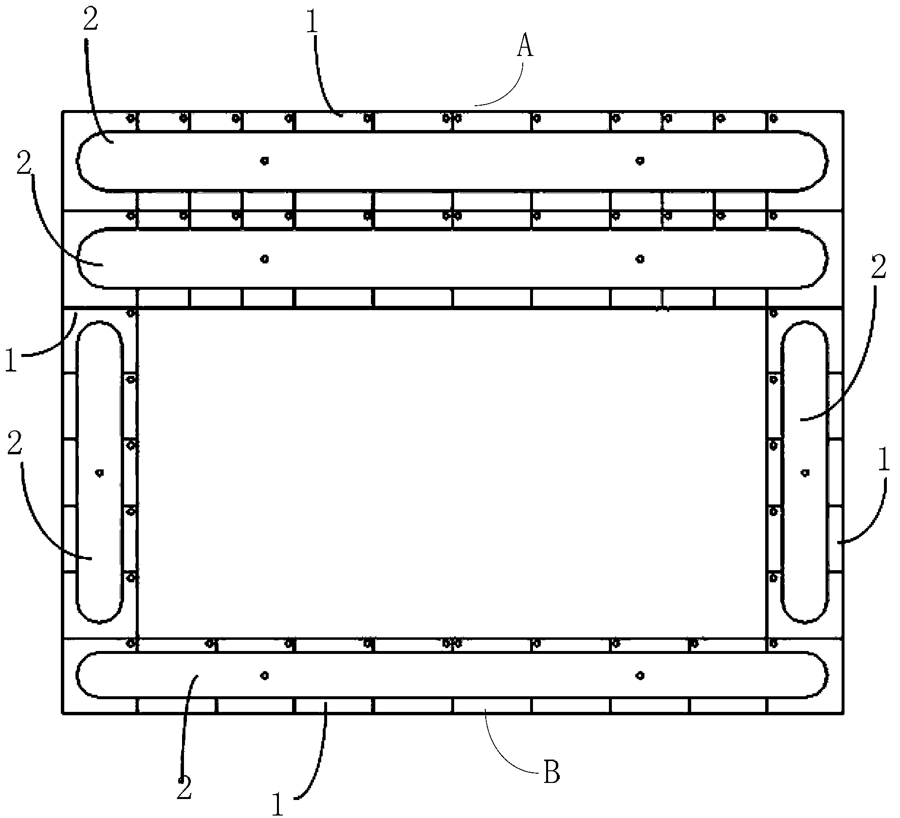
[0019] see figure 1 , The embodiment of the present invention provides an underwater floating body. The underwater floating body is mainly composed of a sub-chamber 1, a pressure-resistant cabin 2, an attitude monitoring system and control equipment. Firstly, the structure of subdivision 1 is introduced. Subdivision 1 is welded by plates of different specifications, specifically: take plates of the same material and thickness, and weld different plates together to form multiple cabins. The plates are selected to be high Strong, corrosion-resistant steel plate. All cabins can be in the shape of a cuboid or a cube, as long as the shape conforms to the design concept of the present invention, it is included in the protection scope of the present invention. Each cabin is a relatively independent closed space. In the actual manufacturing process, a plate with a large area is used as the bottom plate of all cabins. A cabin is called a subdivision1. In this embodiment, all subdivi...


PUM


Abstract

The invention relates to the technical field of ships and particularly relates to an underwater floating body and an installing method thereof. The floating body comprises divided cabins and pressure-resistant cabins, wherein the left side and the right side of the floating body are symmetrically provided with the divided cabins; the front side and the rear side of the floating body are respectively provided with the divided cabin; the buoyancy provided by the divided cabin at the front side of the floating body is larger than that provided by the divided cabin at the rear side of the floating body or the buoyancy provided by the divided cabin at the rear side of the floating body is larger than that provided by the divided cabin at the front side of the floating body. The pressure-resistant cabins penetrate through the divided cabins and are fixedly connected with the cabin walls of the divided cabins. The floating center of the floating body and the gravity center of the floating body are in the same vertical line, and the position of the floating center of the floating body is higher than the position of the gravity center of the floating body. The pressure-resistant cabins are provided with inflation valves, and the divided cabins are provided with venting systems and water introducing systems. The installing method comprises the steps of: inflating the pressure-resistant cabins and filling water into the divided cabins; falling the underwater floating body down to a working water area; inflating air into the divided cabins to discharge a part of water in the divided cabins, and enabling the divided cabin to generate upward buoyancy. According to the underwater floating body and the installing method provided by the invention, the working water area can be reached by one time, so that a great amount of labor and materials is saved.

Description

technical field [0001] The invention relates to the technical field of ships, in particular to an underwater floating body and an installation method thereof. Background technique [0002] Floating production storage and offloading unit (FPSO), as the equipment for the development of offshore oil and gas resources, is widely used in oil and gas development under various water depth conditions. For deep-water floating production storage and offloading (FPSO), the working position of its underwater floating body is generally in deep water, and the outside of the floating body will bear a large water pressure. In order to prevent the structure of the floating body from being damaged due to the high water pressure, it is necessary to allow the inside of the floating body to have a pressure equivalent to the external water pressure. The traditional underwater floating body is designed based on a non-pressure-resistant structure. The floating body structure is a non-pressure-resi...

Claims


Application Information

Patent Timeline
Patent Type & Authority Applications(China)
IPC IPC(8): B63B35/00
CPCB63C11/40B63B35/44B63B2035/448B63G8/22B63G8/36
Inventor 严俊赵耀王宇邵华熊曙
Owner WUCHANG SHIPBUILDING IND
Why Eureka
Try Eureka