Guide structure for control over inversion of tank body

A guiding structure and tank body technology, which is applied in the direction of conveyor objects, transportation and packaging, etc., can solve problems such as difficulty in ensuring the actual weight of canned solids, difficult control of sugar content, and slow production speed

Inactive Publication Date: 2013-12-11
XUZHOU DESHENG PETROLEUM MACHINERY CO LTD
View PDF7 Cites 6 Cited by
  • Summary
  • Abstract
  • Description
  • Claims
  • Application Information

AI Technical Summary

Problems solved by technology

[0002] In the traditional canned fruit production process, there must be a draining process before weighing. Since the raw materials are always soaked in water during the production process of canned fruit, after the raw materials are put into the empty can, there will be a large amount of water in the can. If the residual water in the tank is not drained, it is difficult to ensure the actual weight of the solids in the can, and the sugar content is also difficult to control
Therefore, the operation of arranging workers to drain water is indispensable, but this traditional method of operation has slow production speed and high labor costs

Method used


Image

  • Guide structure for control over inversion of tank body
  • Guide structure for control over inversion of tank body
  • Guide structure for control over inversion of tank body

Examples


Embodiment 1

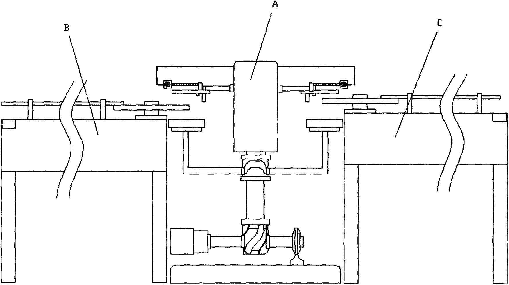
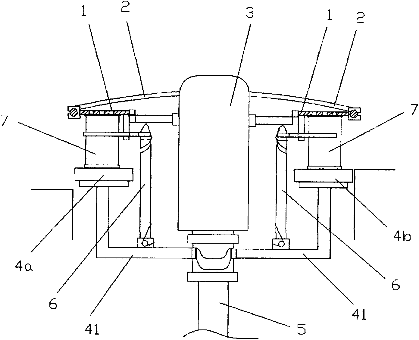
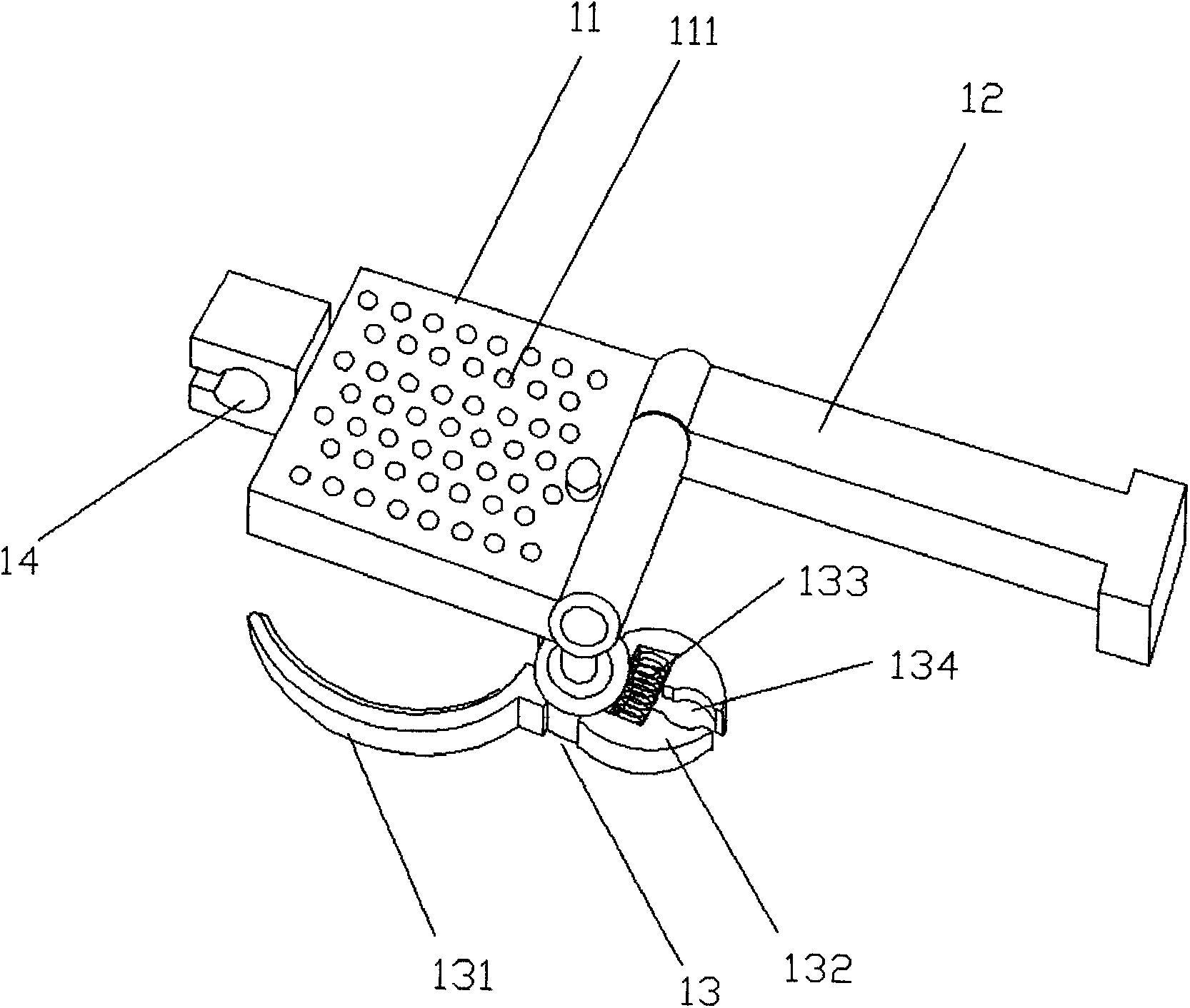
[0027] Embodiment one: if Figure 2-11 As shown, a guiding structure for controlling the inversion of the tank body includes a tank rotating member 1, a track 2, a machine head 3, and a tray. The pallets are the tank-in pallet 4a and the tank-out pallet 4b. The tray and the machine head cooperate with the connected can conveying mechanism to operate. The machine head 3 is connected to the swing rod 12 of the rotating tank member 1, the other end of the swing rod 12 is hinged to the water filtering baffle 11 of the rotating tank member, and the control part 13 for fixing the tank body is connected in parallel to the bottom of the water filtering baffle 11. And corresponding to the tank-in tray 4a and the tank-out tray 4b, a vertical push rod 6 is provided on the horizontal axis 41 of the tank-in tray 4a and the tank-out pallet 4b, and the push rod 6 cooperates with the control member 13, and the water filter baffle plate The opening hole 14 at one end of 11 is sleeved on the ...

Embodiment 2

[0031] Embodiment two: if Figure 7 , 8 , 9, on the straight line from the tank-in pallet 4a to the tank-out pallet 4b, the radian of the track 2 is left-right symmetrical, and the distance H1 between the track 2 above the two pallets and the machine head 3 is a two-phase hinged swing bar 12 and The linear length after the water filter baffle 11 stretches in parallel. The rail 2 is located at the shortest distance H3 from the nose 3, so that the rail 2 leans against the side wall of the nose 3. When the tumbler component 1 slides along the track 2 with the rotation of the machine head 3 until the track 2 is at the closest distance H3 from the machine head 3, that is, when the track is against the side wall of the machine head, the tumbler component 1 is positioned on the track 2, the water filter baffle 11 of the rotary tank member 1 has been rotated at an angle of 180°, the water filter baffle 11 is superimposed on the top of the swing rod 12, and the tank body 7 also stand...


PUM


Abstract

A guide structure for control over the inversion of a tank body comprises a tank rotating component, a track, a handpiece and trays. The trays are arranged on the two sides of the handpiece, connected with a main shaft below the handpiece through a cross shaft, and matched with a tank conveying mechanism connected with the trays for operation. An oscillating bar of the tank rotating component is connected with the handpiece. The other end of the oscillating bar is hinged to a water filtering baffle of the tank rotating component. Control pieces used for fixing the tank body are connected in parallel below the water filtering baffle and correspond to the trays. The track is sleeved with an open pore in one end of the water filtering baffle, and the water filtering baffle rotates in a sliding mode along the track along with the rotation of the handpiece. The track is suspended above the trays and surrounds the handpiece. The guide structure is suitable for production of all types of tanks, is not limited by a tank type mold, and is easy and convenient to operate and thorough in water draining.

Description

technical field [0001] The invention relates to a draining device for draining residual water in a can during the production process of food cans, in particular to a guide structure for a canned drainer to control the inversion of a can body. Background technique [0002] In the traditional canned fruit production process, there must be a draining process before weighing. Since the raw materials are always soaked in water during the production process of canned fruit, after the raw materials are put into the empty can, there will be a large amount of water in the can. If the residual moisture in the cans is not drained, it is difficult to ensure the actual weight of the solids in the cans, and the sugar content is also difficult to control. Therefore, it is indispensable to arrange the operation of workers to drain the water, but this traditional method of operation has slow production speed and high labor cost. [0003] In order to overcome the shortcomings of the above-me...

Claims


Application Information

Patent Timeline
IPC IPC(8): B65G47/248
Inventor 胡海明
Owner XUZHOU DESHENG PETROLEUM MACHINERY CO LTD
Why Eureka
Try Eureka